Module mounting/removing mechanism and disk array

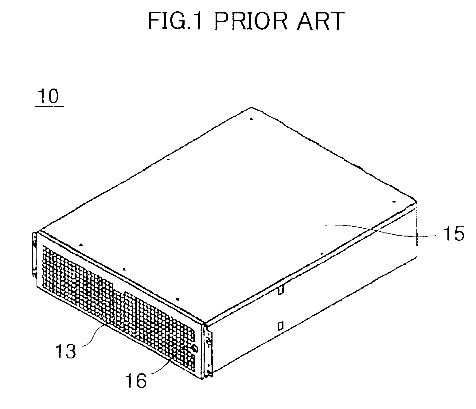
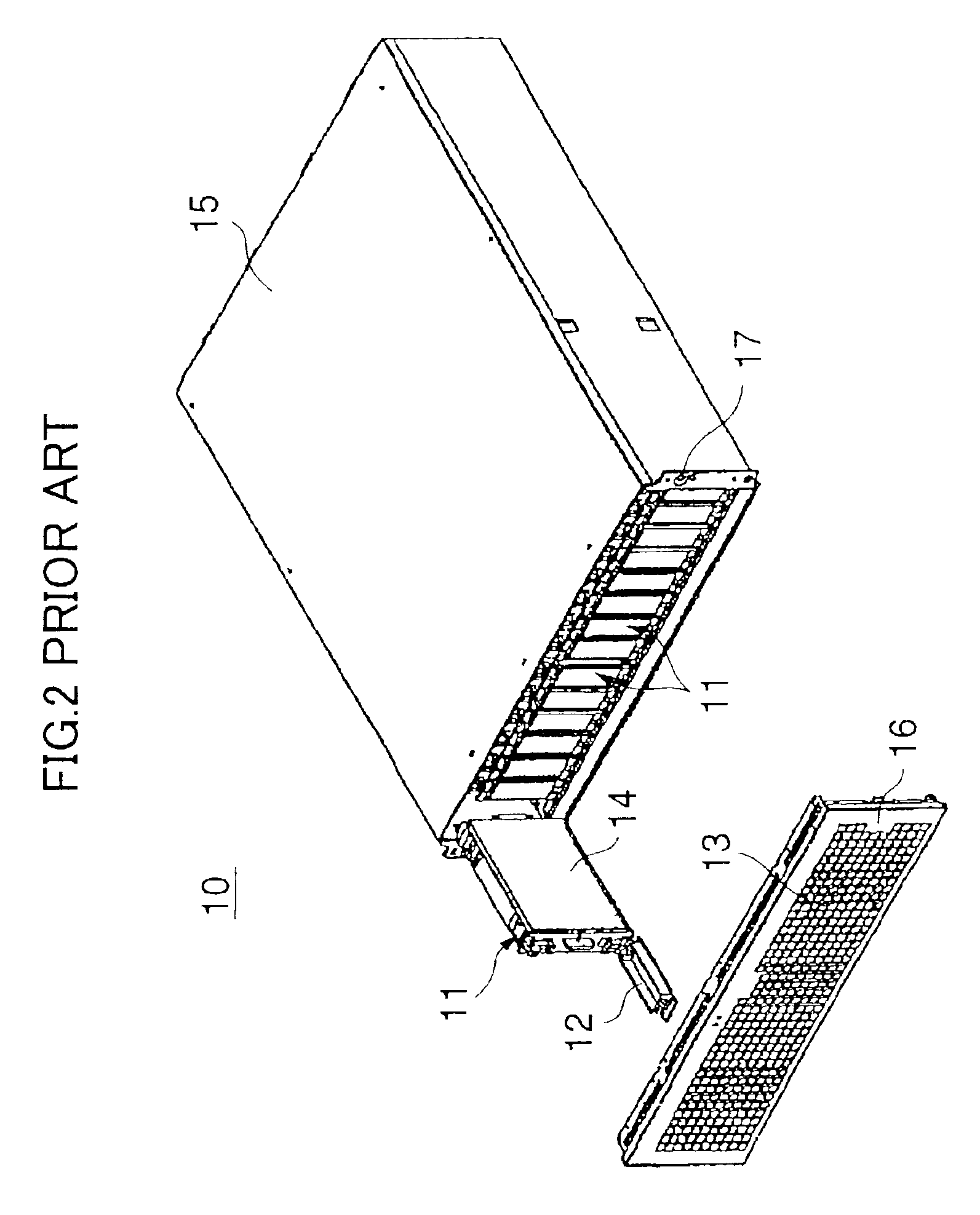
a module and mounting mechanism technology, applied in the direction of instruments, furniture parts, electrical apparatus casings/cabinets/drawers, etc., can solve the problems of data or various devices being damaged, the module(s) or the disk array device may be mounted or removed, and the data or various devices may be damaged, etc., to reduce the number of components, simple and convenient, and easy to release

Inactive Publication Date: 2005-10-04
FUJITSU LTD
View PDF32 Cites 71 Cited by
  • Summary
  • Abstract
  • Description
  • Claims
  • Application Information

AI Technical Summary

Benefits of technology

[0021]With the invention described above, since the lever member has a dual function as a cover and as a grip part, the disk array apparatus can be manufactured with a reduced number of components. Also, since the lever member serves as a cover, an operation of removing the cover from the holder and an operation of moving the lever member into the second position can be performed in a single operation. Therefore, the module can be mounted to and / or removed from the enclosure in a simple and facilitated manner. Further, with an operation button, the engagement of the lever member by the engagement mechanism can be easily released. This also facilitates the operation of mounting and removing the module to and from the enclosure.
[0022]The lever member of the present invention is provided with cooling holes. Therefore, electronic devices that may be contained in the modules can be cooled in an efficient manner.
[0023]The disk array apparatus of the present invention is also provided with a keylock mechanism. Therefore, the modules can be prevented from being mistakenly removed from the enclosure.

Problems solved by technology

Further, if a third person has free access to the disk array device, the module(s) could be inadvertently detached from the disk array device during a recording or reproducing operation.
This may result in damage of data, the module(s) or the disk array device.
Further, as has been described above, if the module 11 can be freely mounted to or removed from the enclosure 15, the data or various devices may be damaged due to an inadvertent mounting or removing operation.
Therefore, it is troublesome to mount or remove the module 11 and it gives rise to poor operability.
This also gives rise to poor operability.
With such a structure, the disk array device 10 becomes bulky due to the thickness of the bezel cover 13.

Method used


Image

  • Module mounting/removing mechanism and disk array
  • Module mounting/removing mechanism and disk array
  • Module mounting/removing mechanism and disk array

Examples


Embodiment Construction

[0046]In the following, principles and embodiments of the present invention will be described with reference to the accompanying drawings.

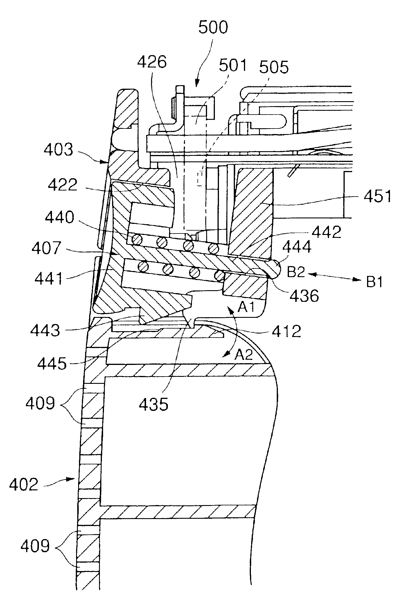
[0047]FIG. 3 is a perspective diagram showing a disk array device 20 having a module mounting / removing mechanism of an embodiment of the present invention. FIG. 4 is an exploded perspective diagram showing a major part of the disk array device 20. The disk array device 20 is an auxiliary storage device of a mainframe computer and is mainly used as a data backup storage device.

[0048]As can be seen in FIGS. 3 and 4, the disk array device 20 generally includes an enclosure 300, a plurality of modules 400 and a security lock part 500.

[0049]The enclosure 300 is configured such that the plurality of modules 400 can be mounted thereto and removed therefrom. As can be seen in FIG. 4, an opening part 302 is formed on the front face of the enclosure 300. The modules 400 can be mounted and removed via the opening part 302. A partition wall 303 is provided at...


PUM

PropertyMeasurementUnit
areaaaaaaaaaaa
movementaaaaaaaaaa
speedaaaaaaaaaa

Abstract

A disk array apparatus includes an enclosure having an opening at its front face, at least one module configured to be mounted in the enclosure and at least one securing mechanism configured to secure the at least one module to the enclosure. The module includes a frame member and a lever member that is movable between a first position received by the frame member in which it serves as a cover of the opening and a second position in which it serves as a grip part for pulling the module out of the enclosure.

Description

BACKGROUND OF THE INVENTION[0001]1. Field of the Invention[0002]The present invention generally relates to a module mounting / removing mechanism and particularly relates to a disk array device in which a plurality of detachable hard disk drive devices can be loaded.[0003]2. Description of the Related Art[0004]There has been a need for a mass storage external storage device that can be accessed at high speed with high reliability. In order to provide such an external storage device, a disk array device is known in which a plurality of modules each containing a hard disk drive device (HDD) can be loaded. For the maintenance of such a disk array device, one or more of the modules (hard disk drive device) requiring maintenance are replaced while the disk array device as a whole remains in operation.[0005]Further, if a third person has free access to the disk array device, the module(s) could be inadvertently detached from the disk array device during a recording or reproducing operation....

Claims


Application Information

Patent Timeline
Patent Type & Authority Patents(United States)
IPC IPC(8): G11B33/02G11B33/12G06F1/16H05K7/14
CPCG11B33/022G11B33/128
Inventor HIDAKA, HIROSHIYAMAMOTO, TAKASHIKORIKAWA, MASAYUKIKATANO, KATSUHISA
Owner FUJITSU LTD
Why Eureka
Try Eureka