Fastener driving tool having contact arm in contact with workpiece

a technology of driving tool and workpiece, which is applied in the direction of manufacturing tools, stapling tools, nailing tools, etc., can solve the problems of affecting the operation of the tool, the free end of the contact arm may be tangled or abutted, and the free end of the contact arm may damage the attachment member, so as to reduce accidental injuries and sufficiency of operation and workability

Active Publication Date: 2005-10-11
KOKI HLDG CO LTD
View PDF11 Cites 49 Cited by
  • Summary
  • Abstract
  • Description
  • Claims
  • Application Information

AI Technical Summary

Benefits of technology

[0008]It is therefore an object of the present invention to overcome the above-described problems and to provide an improved nail gun providing sufficient operability and workability and capable of lowering accidental injury on the attachment member by a free end of the contact arm during shifting of the nail gun to a next shooting position in sequential nail driving operation.

Problems solved by technology

Consequently, the free end of the contact arm may be tangled or abutted against walls of the grooves of the attachment member to damage to the contact arm and the attachment member.
Accordingly, the nail gun must be further moved toward the attachment member by the moving stroke of the contact arm, whereupon moving impact force is generated so that the free end of the contact arm may damage to the attachment member.

Method used


Image

  • Fastener driving tool having contact arm in contact with workpiece
  • Fastener driving tool having contact arm in contact with workpiece
  • Fastener driving tool having contact arm in contact with workpiece

Examples


Embodiment Construction

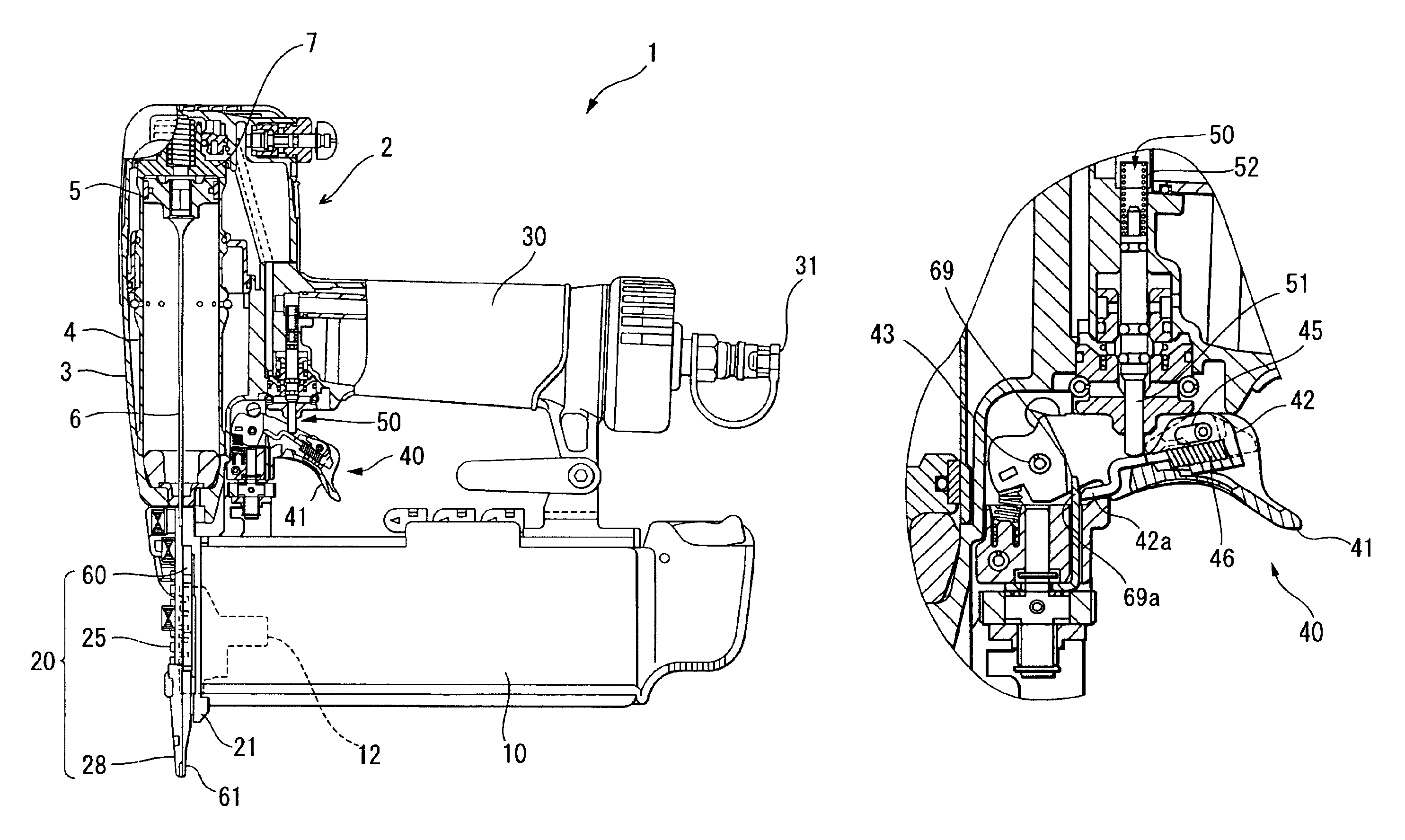
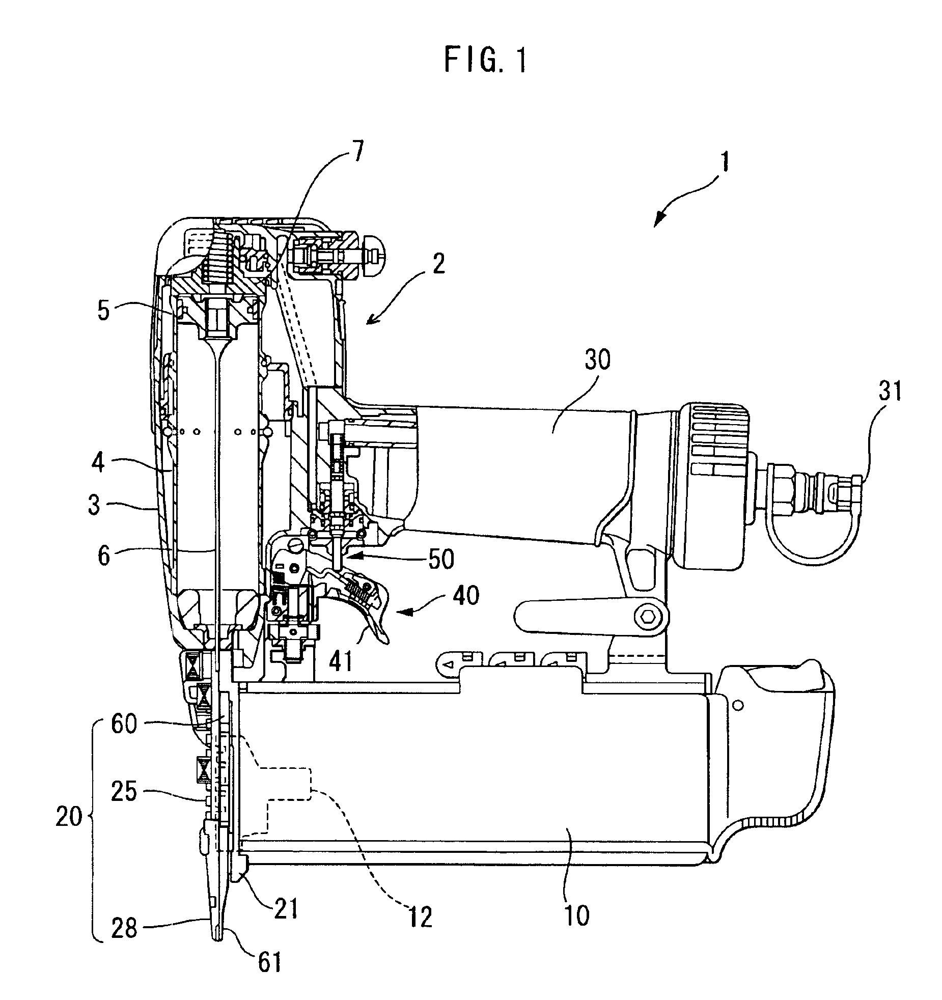
[0021]A nail gun according to one embodiment of the present invention will be described with reference to FIGS. 1 through 10. As shown in FIG. 1, the nail gun 1 generally includes a main driving section 2 including a main housing 3, a magazine 10, a nail injection section 20, a handle 30, a trigger mechanism 40, a switch mechanism or a trigger valve mechanism 50 and a contact arm 60. The handle 30 extends from the main housing 3 in a direction substantially perpendicular thereto. The injection section 20 extends from a lower side of the main housing 3 in a longitudinal direction of the main housing 3. The magazine 10 extends substantially in parallel with the handle 30 and is supported between the handle 30 and the injection section 20. The trigger mechanism 40 is provided nearby a base end portion of the handle 30. The trigger mechanism 40 has a trigger 41 supported to the main housing 3 at a position surrounded by the main housing 3, the magazine 10 and the handle 30. The trigger ...


PUM

PropertyMeasurementUnit
thicknessaaaaaaaaaa
biasing forceaaaaaaaaaa
widthaaaaaaaaaa

Abstract

A nail gun having a contact arm normally biased in a direction away from a workpiece by compression springs. A free end of the contact arm is brought into abutment with a workpiece and a trigger is pulled for driving a nail thereinto. In the trigger pulling operation, an inner end of the contact arm is engaged with a trigger arm which is biased by a plunger spring through a plunger. Because the contact arm is held on the workpiece, the plunger is moved to provide ON state against biasing force of the plunger spring. Immediately after the nail driving, a nail gun body is moved in a direction away from the workpiece relative to the contact arm. This causes disengagement of the trigger arm from the inner end, to relatively move the nail gun body toward the workpiece by the biasing force of the compression springs. This means relative movement of the contact arm in the direction away from the workpiece. If the trigger is released, the trigger arm is again brought into engagement with the inner end, because the trigger arm is normally urged toward the inner end by a trigger arm spring.

Description

BACKGROUND OF THE INVENTION[0001]The present invention relates to a fastener driving tool such as a nail gun, and more particularly, to the nail gun electrically or pneumatically operated for providing a fine appearance on a workpiece after nail fastening.[0002]Attachment members or finishing materials for use in a baseboard for trimming purposes or for a verandah running on more than two sides of a house or room are adhesively fixed to a wall, and then fixed by fasteners such as nails. A groove having a predetermined small width is formed in the attachment member, and the nails are driven into the groove. The nails have a head portion whose color is selected to be in conformance with the external color of the attachment member. Further, the head portion of the nail has a small diameter, so that the head portion can be positioned onto a bottom of the small width groove in an attempt to obtain good external appearance on the attachment member without any scratches as bruises after th...

Claims


Application Information

Patent Timeline
Patent Type & Authority Patents(United States)
IPC IPC(8): B25C1/00B25C7/00B25C1/04
CPCB25C1/008
Inventor NAKANO, YOSHIHIROTANJI, ISAMU
Owner KOKI HLDG CO LTD
Why Eureka
Try Eureka