
Extruder head

a technology of extruder and head, which is applied in the field of extruder head, can solve the problems of not providing

Inactive Publication Date: 2005-10-11
FEUERHERM MAX
View PDF4 Cites 22 Cited by
  • Summary
  • Abstract
  • Description
  • Claims
  • Application Information

AI Technical Summary

Benefits of technology

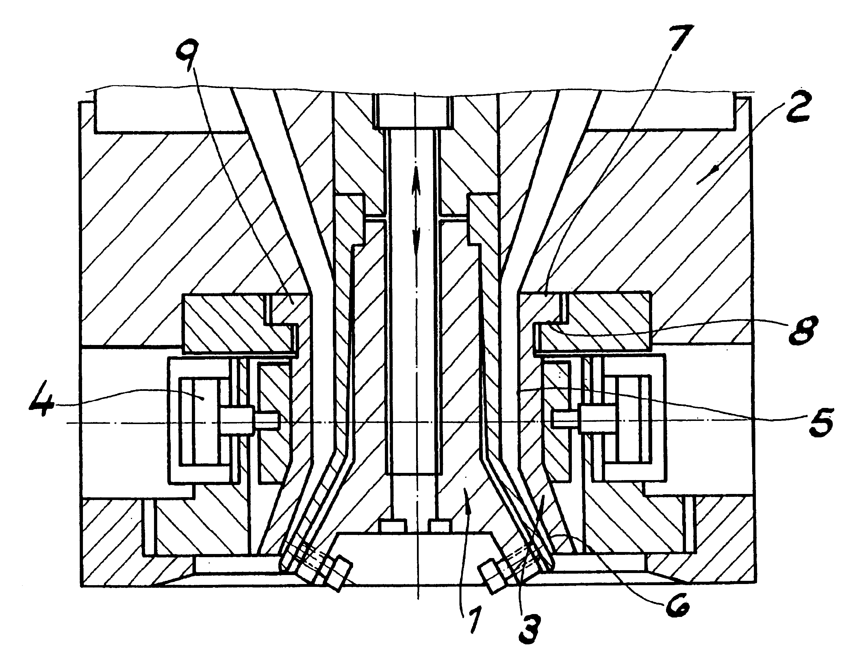
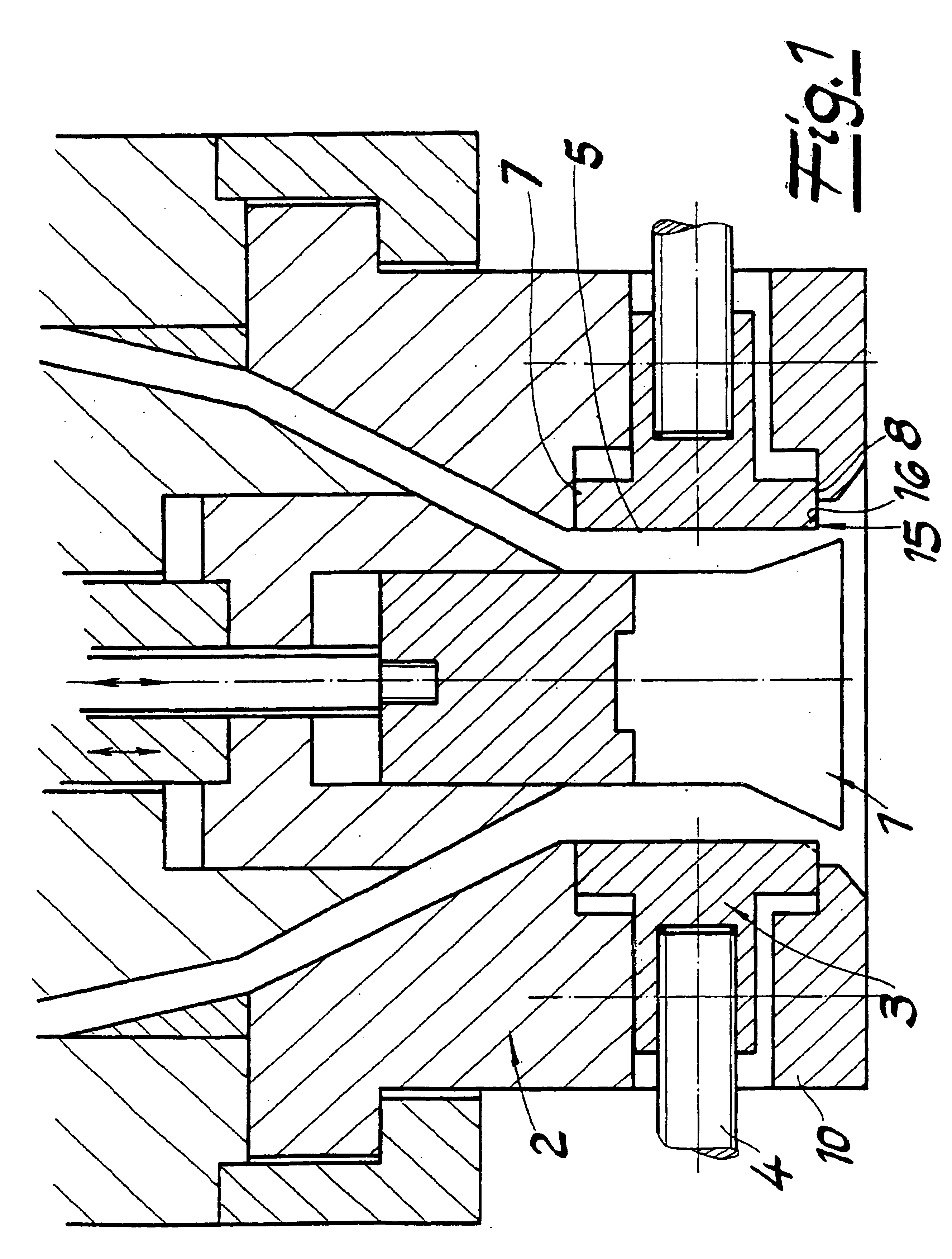
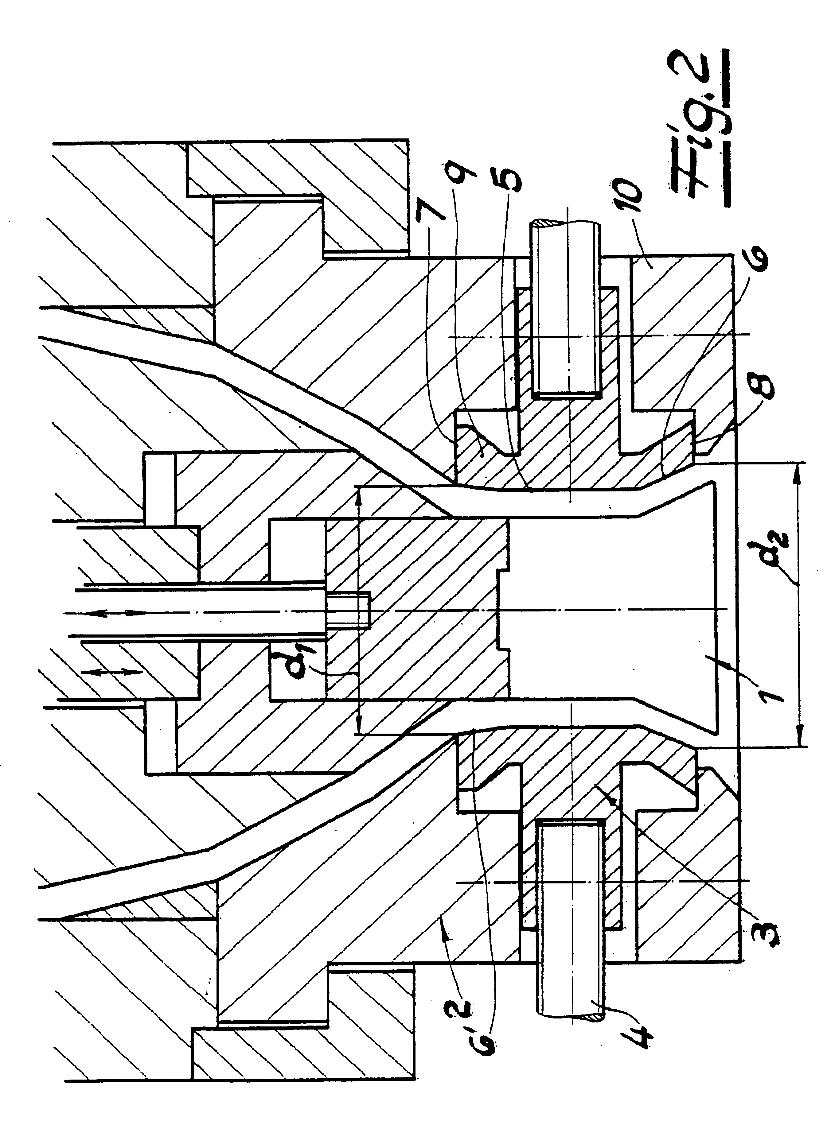
"The invention is about improving an extruder head by using a cylindrical or conical sleeve that is shaped to influence the geometry of the melt channel. The sleeve is designed to be deformed and displaced at the end of the nozzle outlet side, allowing for wear-free deformations and displaced melt exit. The lower edge of the sleeve is rounded off or has a conical profile to improve the smoothing effect and achieve superior blow-molding results. The invention also includes a method for compensating for axial forces acting on the sleeve by using a conical widening of the sleeve. Overall, the invention provides a solution for improving the extrusion process and achieving high-quality plastic containers."

Problems solved by technology

The molding pressure prevailing in the melt channel is axially transmitted to the sleeve, so that the technical problem explained above arises in connection with the present design as well.
The prior art does not provide any suggestions to the extent that a cylindrical or at least approximately cylindrical sleeve be employed on the orifice of the nozzle that is continuously subjected to constantly changing deformations by preferably program-controlled setting devices as the hose being molded is exiting, and whose lower edge shapes the cross-section of the stream of melt as the latter is exiting from the ring-gap nozzle.

Method used


Image

  • Extruder head
  • Extruder head
  • Extruder head

Examples


examples

[0054](1) The sleeve shown in FIG. 3 has the following values:

[0055]

Length:60.0mmWall thickness of sleeve:5.0mmCross-sectional area A1 of upper collar:70.7mm2Cross-sectional area A2 of lower collar:12.0mm2Spacing of point of force application34.2mmmeasured on lower edge of sleeve:Moment of area deviation Iyz:−13.7mm4Moment of area inertia Iy:161,405.7mm4Moment of area inertia Iz:5,993.1mm4[0056](2) The sleeve shown in FIG. 4 has a length of 60.0 mm and a wall thickness of 9.0 mm in the cylindrical section.

[0057]The following values are obtained for the moment of area deviation and the moments of inertia:

[0058]

Moment of area deviation Iyz:−10,408.9mm4Moment of area inertia Iy:138,497.1mm4Moment of area inertia Iz:4,196.8mm4

The point of force application by the setting devices lies above the cross-sectional plane in which the center of gravity of the area is located.


PUM

PropertyMeasurementUnit
widthaaaaaaaaaa
diameteraaaaaaaaaa
heightaaaaaaaaaa

Abstract

An extruder head for extrusion blow-molding plastic containers includes a ring gap nozzle with a mandrel and a ring-shaped nozzle body. An elastically deformable sleeve is arranged on an end of the nozzle outlet side and defines a gap width which can be varied by axial setting movements of the mandrel and / or the nozzle body. The geometry of the nozzle gap can be influenced by radially deforming the sleeve with setting devices during the extrusion of a hose-shaped preformed blank. The sleeve may be moved in a radial direction and is guided on sliding surfaces which support it in upward and downward directions. The sleeve may be in the form of a cylinder or tube. A lower edge of the sleeve shapes a cross-section of a melt stream exiting from the ring gap nozzle.

Description

CROSS-REFERENCE TO RELATED APPLICATIONS[0001]Applicants claim priority under 35 U.S.C. §119 of GERMAN Application No. 199 31 870.0 filed on Jul. 9, 1999.BACKGROUND OF THE INVENTION[0002]1. Field of the Invention[0003]The invention relates to an extruder head for extrusion blow-molding plastic containers, comprising[0004]a ring-gap nozzle having a mandrel and a ring-shaped nozzle body;[0005]an elastically deformable sleeve; and[0006]setting devices for deforming the elastic sleeve radially.whereby the sleeve arranged on the outlet side of the nozzle defines a nozzle gap whose width is variable by axial setting movements of the mandrel and / or body of the nozzle, and whose geometry can be influenced by deforming the sleeve in the course of extrusion of a hose-like preformed blank; and whereby the sleeve is guided with radial mobility on sliding surfaces that support the sleeve upwards and downwards.[0007]2. Prior Art[0008]An extrusion head with the features described above is known fro...

Claims


Application Information

Patent Timeline
Patent Type & Authority Patents(United States)
IPC IPC(8): B29C47/22B05B1/32B05B3/04B29C48/09B29C48/325
CPCB29C47/0026B29C47/22B29C47/225B29C48/10B29C48/325B29C48/327B29C48/09
Inventor FEUERHERM, HARALDKAPPEN, GUNTHER
Owner FEUERHERM MAX
Learn More