Electric box extender

a box extender and electric technology, applied in the field of electric boxes, can solve the problems of cumbersome shipping of such box extenders, difficult installation of known box extenders, cumbersome installation of such extenders, etc., and achieve the effect of simple structure and positive operation

Active Publication Date: 2005-10-11
BRIDGEPORT FITTINGS LLC
View PDF13 Cites 40 Cited by
  • Summary
  • Abstract
  • Description
  • Claims
  • Application Information

AI Technical Summary

Benefits of technology

[0005]An object of this invention is to provide an electric box extender that is relatively simple in structure and positive in operation.
[0006]Another object is to provide an electric box extender that can be readily installed in a relatively simple manner and with a minimum of effort.
[0013]In another modified embodiment of the invention, the electric box extender at the inner end thereof is provided with a laterally inwardly extending circumscribing rear flange defining a rear opening and against which an electric device, e.g. a GFCI device, abuts. The rear flange is also provided with opposed notches for accommodating the ends of the wire conductors which are retained by the push-in captive lugs in the back side of the GFCI electric device. If desired, this modified embodiment may be further modified by having the opposed sides of the body portion tapered inwardly whereby like box extenders may be nested or stacked one within the other to facilitate shipping, handling, and / or the storage thereof.

Problems solved by technology

It has also been noted that, frequently, difficulty has been encountered in the installation of the known box extenders due to the requirement of the need to align the various screw openings of the assembled parts for securing the electric box extender to the installed electric box.
As a result, the installation of such extenders is tedious and time consuming.
Because of the construction of such prior known electric box extenders, the shipping of such box extenders is cumbersome in that such box extenders, having integrally formed tubular walls, are generally loosely shipped in large cartons or had to be individually packaged in a box to prevent damage in shipment.
Such packaging only served to increase the cost of those box extenders having relatively rigid integrally formed walls to the ultimate consumers.

Method used


Image

  • Electric box extender
  • Electric box extender
  • Electric box extender

Examples


Embodiment Construction

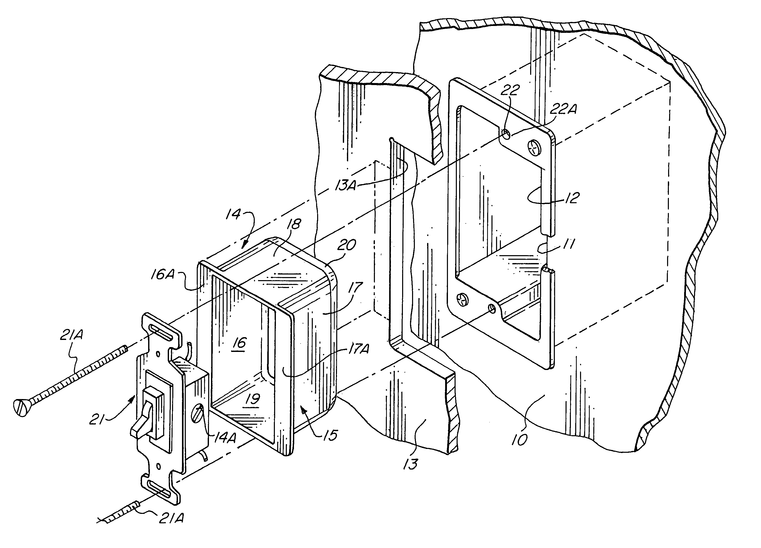
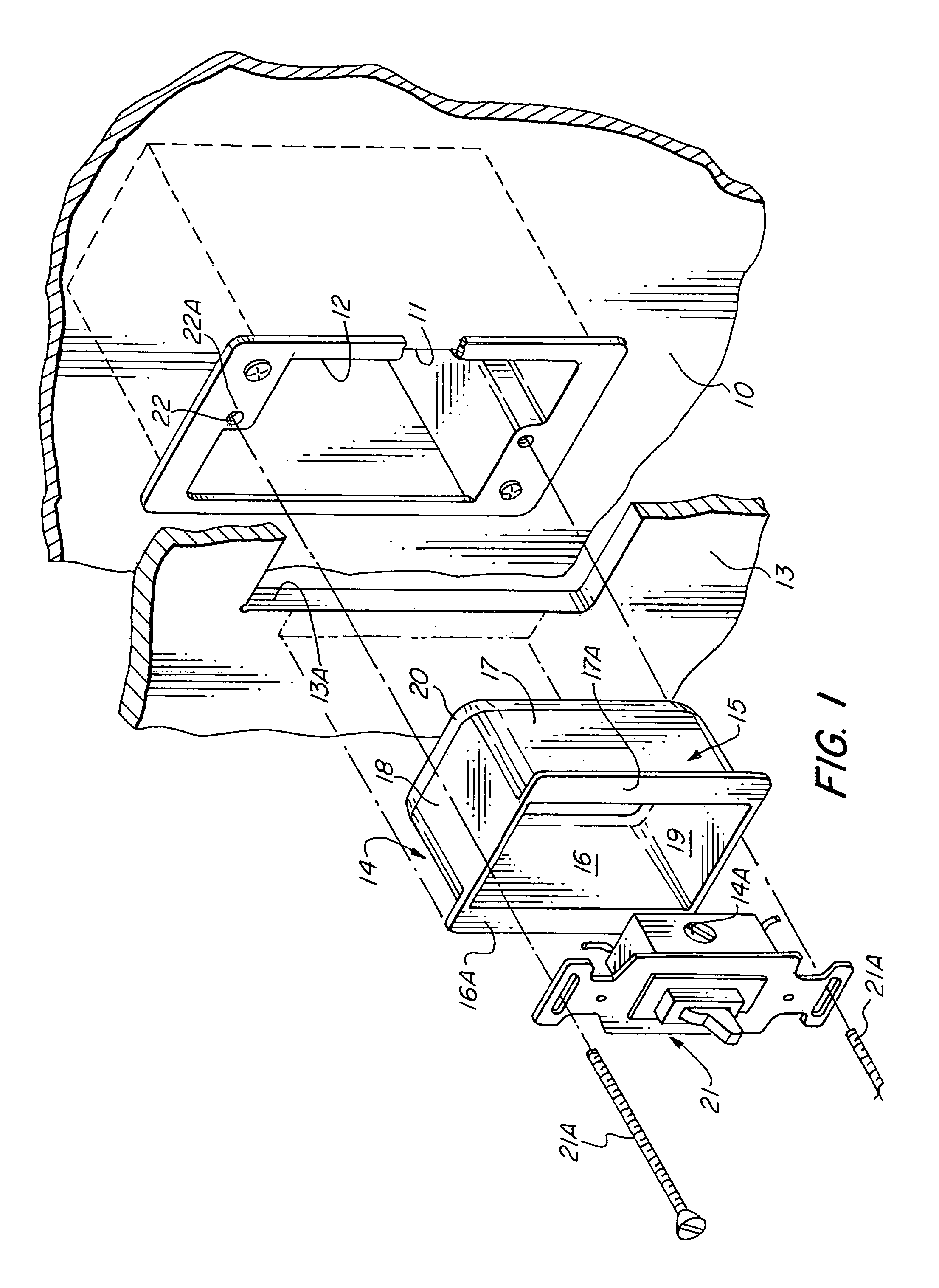
[0030]Referring to the drawings, there is shown in FIG. 1 a wall 10 having a wall opening 11 and a typical electric box 12 mounted in alignment with the wall opening 11 and secured by suitable fasteners. While one type of electric box is shown in the drawings, the specific type of electric box is not critical. In the event the wall 10 is resurfaced with a new or covering wall surface 13, code and safety requirements mandate that the electric box, e.g. box 12, be located flush with the new wall. Because it is difficult, if not impossible, to relocate the electric box 12 secured with respect to the old wall, this invention provides for a box extender 14 which is adapted to be received within the electric box 12 and which, together with the electric box 12, effectively functions as an electric box which is rendered flush with the new wall 13 to satisfy any code requirements.

[0031]As shown in FIG. 1, the new wall 13 is provided with an opening 13A which is in alignment with the opening ...


PUM


Abstract

An electric box assembly that includes a box extender having a tubular body with opposed sides arranged to be received within an electric box, and which box extender is formed with a pair of laterally outwardly extending face flanges arranged to be flush mounted against a wall surface in the assembled position. The box extender is devoid of any top or bottom flanges and is adapted to be secured in place within an electric box by the electric device, outlet receptacle, switch or the like. In an embodiment of the invention, the sides of the tubular body are tapered inwardly toward the central axis of the tubular body so as to permit the box extender to be nested one within the other to facilitate shipping and handling.

Description

FIELD OF THE INVENTION[0001]This invention relates generally to electric boxes and more specifically to electric box extenders or an insulating barrier for use with and / or in combination with electric boxes which are mounted in a fashion where the electric box is recessed in a wall surface.BACKGROUND OF THE INVENTION[0002]Heretofore, a number of electric box extenders have been marketed by various competing manufacturers such as Bridgeport Fittings, Inc., Arlington Industries, Carlon, Inc. and perhaps others. All of the known or available box extenders are generally similar in construction in that the known box extenders include a circumscribing face plate having rearwardly connected extending sides or wings defining a body portion arranged to be received into an existing installed electric box to form an extension thereof, and whereby the face flange of the box extender is provided with one or more screw openings that are required to be in alignment with the screw opening of the fl...

Claims


Application Information

Patent Timeline
Patent Type & Authority Patents(United States)
IPC IPC(8): H01H9/02H02G3/12H02G3/14H02G3/08H01H73/06
CPCH02G3/086Y10S248/906
Inventor UNGERMAN, MARK E.KIELY, KENNETH M.
Owner BRIDGEPORT FITTINGS LLC
Why Eureka
Try Eureka