Disk chuck

a technology of disk chuck and chuck, which is applied in the direction of track finding/aligning, instruments, fastening means, etc., can solve the problems of inconvenient use of conventional disk chucks and inability to store data or programs on such disks, and achieve the effect of easy and simple clamping and unclamping

Inactive Publication Date: 2005-10-11
SAMSUNG ELECTRONICS CO LTD
View PDF13 Cites 20 Cited by
  • Summary
  • Abstract
  • Description
  • Claims
  • Application Information

AI Technical Summary

Benefits of technology

[0011]Accordingly, it is an object of the present invention to provide a disk chuck which allows an operator to easily and simply clamp and unclamp a plurality of disks during a disk formatting process.
[0018]According to an aspect of the present invention, the disk clamping part comprises a skirt part which extends from the upper end of the clamping shaft toward the upper end of the hollow main shaft by a predetermined length and includes an outer diameter which is larger than that of the clamping shaft, and slits which are formed on the skirt part in a radial direction and allow the outer diameter of the skirt part to be changeable wherein the upper end of the hollow main shaft includes a chamfered surface which allows the skirt part to expand to enlarge the outer diameter of the skirt part and to compress the disks fitted over the hollow main shaft during a downward movement of the clamping shaft.
[0021]Each of the spacers comprises an outside member which includes a seat opening having a stepped inner surface, an inside member which is movably seated in the outside member so as to be retractable relative to the outside member and includes an external top surface having a tapered disk seat surface which fits and centers a corresponding one of the disks, a spring which is set between the inside and outside members and biases the inside member relative to the outside member so as to normally expose the tapered disk seat surface of the inside member outside the outside member, and a stop ring which is set in the seat opening of the outside member and prevents a removal of the inside member from the outside member.

Problems solved by technology

However, it is impossible to store data or programs on such disks unless they are formatted after they are manufactured.
This labor-intensive process is repeated for each disk formatting process and makes the conventional disk chuck inconvenient to use.
Therefore, the pin 5 may fail to precisely center the disks 4, causing an error during a disk formatting process.

Method used


Image

  • Disk chuck
  • Disk chuck
  • Disk chuck

Examples


Embodiment Construction

[0030]Reference will now be made in detail to the present preferred embodiments of the present invention, examples of which are illustrated in the accompanying drawings, wherein like reference numerals refer to like elements throughout

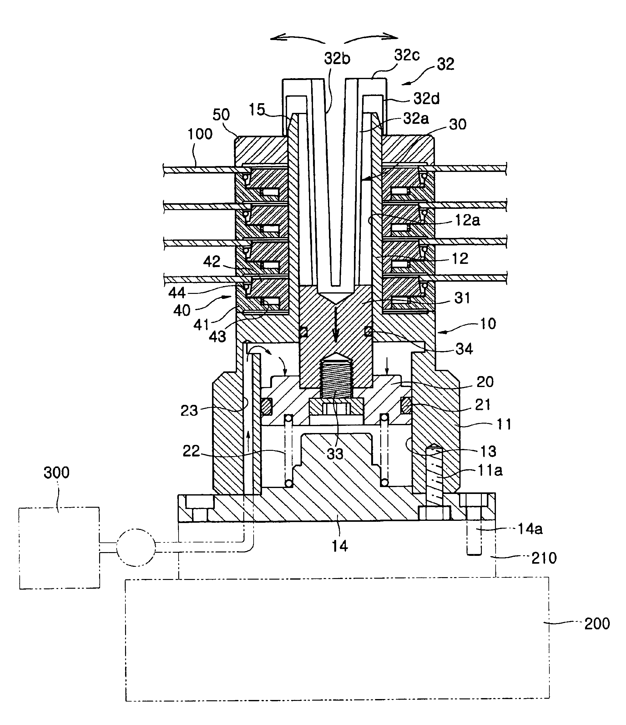
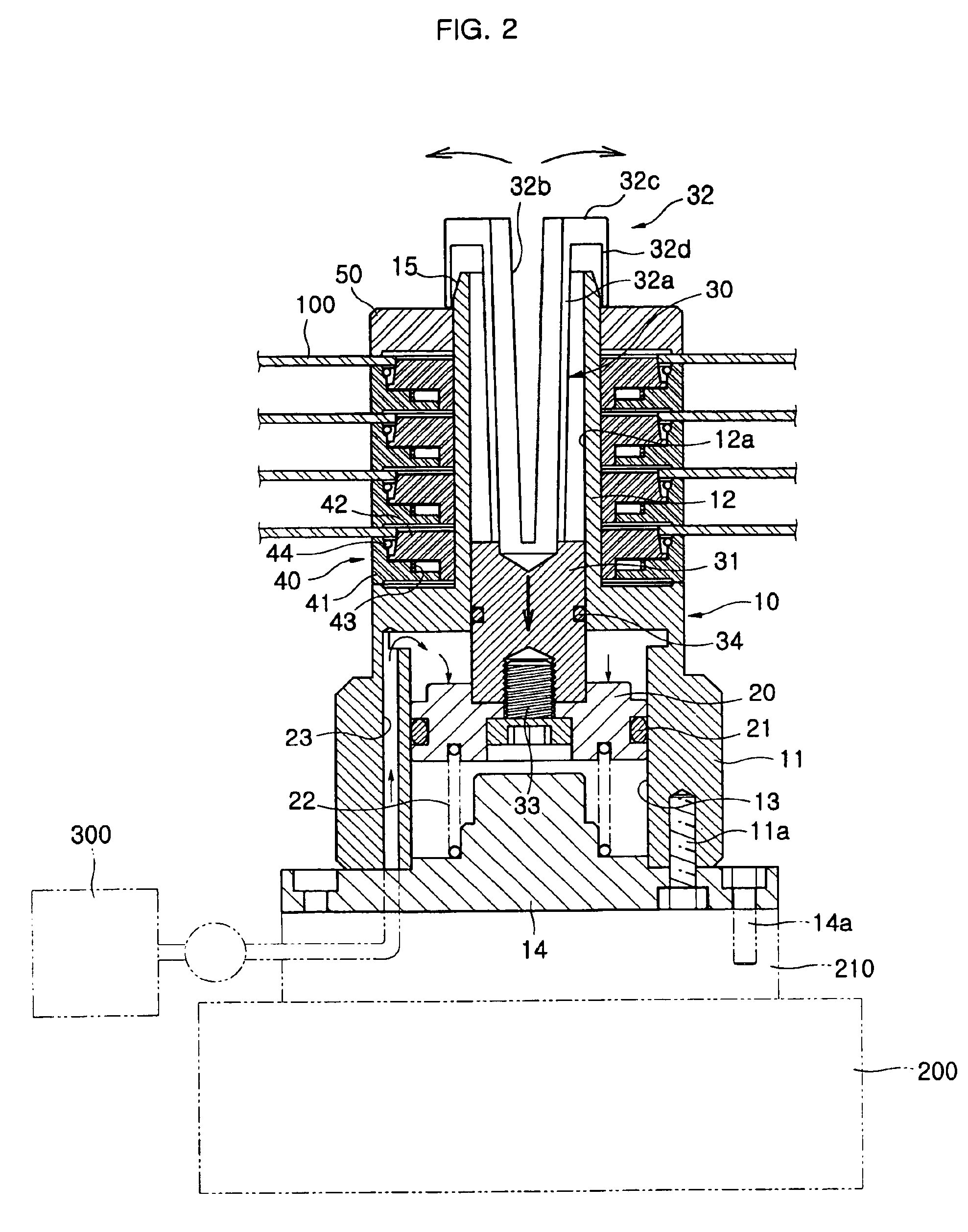
[0031]FIG. 2 shows the construction of a disk chuck according to an embodiment of the present invention. The disk chuck comprises a hollow main shaft 10 which is coupled to a rotating shaft 210 of a spindle motor 200 and seats disks 100 thereon so as to orderly fit the disks 100 over the hollow main shaft 10. The disk chuck further comprises a disk clamping unit which clamps the disks 100 that are fitted over the hollow main shaft 10, a plurality of spacers 40 which allow the disks 100 to be regularly spaced apart from each other and precisely centered on the hollow main shaft 10 as the disks 100 are clamped on the hollow main shaft 10, and a top cover 50 which covers a portion of an uppermost disk of the disks 100 when the disks 100 are clamped on the...


PUM

PropertyMeasurementUnit
outer diameteraaaaaaaaaa
diameteraaaaaaaaaa
areaaaaaaaaaaa

Abstract

A disk chuck which centers and clamps data storage disks during a disk formatting process. The disk chuck is designed to clamp or unclamp the disks at the same time. The disk chuck includes a hollow main shaft which orderly fits and seats the disks thereon and a piston which is situated in the hollow main shaft so as to axially move in the hollow main shaft in opposite directions. A clamping shaft is axially received in the hollow main shaft and coupled to the piston so as to move along with the piston in the same direction to clamp or unclamp the disks seated on the hollow main shaft. An upper end of the clamping shaft having a disk clamping part extends to project beyond an upper end of the hollow main shaft.

Description

CROSS-REFERENCE TO RELATED APPLICATIONS[0001]This application claims the benefit of Korean Application No. 2001-76070, filed Dec. 4, 2001, in the Korean Patent Office, the disclosure of which is incorporated herein by reference.BACKGROUND OF THE INVENTION[0002]1. Field of the Invention[0003]The present invention relates to disk chucks which center and clamp data storage disks and, more particularly, to a disk chuck designed to clamp or unclamp a plurality of disks at the same time.[0004]2. Description of the Prior Art[0005]In general, data storage disks such as magnetic disks for hard disk drives (HDD) of computers store data and programs thereon for a later retrieval. However, it is impossible to store data or programs on such disks unless they are formatted after they are manufactured. During a disk formatting process, tracks are densely formed on a disk and are sectored, thus allowing the disk to effectively store the data and programs.[0006]In an effort to quickly perform such a...

Claims


Application Information

Patent Timeline
Patent Type & Authority Patents(United States)
IPC IPC(8): G11B17/02G11B17/038F16B2/06G11B17/028G11B21/10
CPCG11B17/038G11B17/028
Inventor YEOM, KI-KEON
Owner SAMSUNG ELECTRONICS CO LTD
Why Eureka
Try Eureka