
Insulation support for roof insulation applicator

a technology for roof insulation and applicators, which is applied in the direction of roofs, building materials handling, construction, etc., can solve the problems of lack of experience and capability of installers, affecting the installation process, and the center portion of sheets without support, etc., and achieves the effect of less effor

Inactive Publication Date: 2005-10-18
ALDERMAN ROBERT J
View PDF13 Cites 8 Cited by
  • Summary
  • Abstract
  • Description
  • Claims
  • Application Information

AI Technical Summary

Benefits of technology

[0015]In one embodiment of the invention, the rear segment and side segments of the sheet support form elongated slots therebetween that register with the purlins, so that the rear segment and side segments of the sheet support can extend all the way back from the carriage into the space where the next hard roof panel is to be installed, so that even as the panel is being fastened down to the purlins, the sheet support is in its supportive position beneath the flexible sheet material and beneath the panel that is being installed. In the meantime, the sheet support is resting on the purlins so that the exact desired height of the rear segment and side segments of the sheet support is attained, thereby providing optimum support for the flexible sheet material as it is being installed in the roof structure.
[0016]Typically, a plurality of the roof insulation support carriages would be mounted on the roof structure at one time, in two lines or rows, with the first or front row of carriages mounted on the purlins of every other space between the purlins, and a second or rear row of carriages mounted on the purlins at the other alternate spaces between the purlins. The sheet supports are required only on the rear row of carriages since the side segments of the sheet supports extend out into the alternate spaces over which the forward carriages are mounted. This has the advantage of utilizing only one-half the number of sheet supports as well as having the sheet supports of one size and configuration to serve the entire roof structure. Also, since the sheet supports are used with the second row of carriages, the sheet supports are used close to the installers that stand on the roof panels, thereby requiring less effort to handle the sheet supports during installing and using the sheet supports on the purlins.
[0017]Thus, it is an object of this invention to provide a sheet support for use with a roof insulation support carriage for accurately and expediently applying flexible sheet material, such as blanket insulation, to the purlins of a roof structure.
[0018]Another object of this invention is to provide an improved sheet support that is suitable for use with the second row of roof insulation support carriages that provides accurate support for flexible sheet material being applied to the roof structure by the carriages in both the first and second rows of carriages.
[0020]Another object of the invention is to provide a combination of a carriage for applying sheet material to purlins of a roof of an industrial building and a sheet support for accurately supporting the sheet material paid out from the carriage at the desired level to avoid sagging of the sheet material between the purlins.

Problems solved by technology

One of the problems that is encountered in applying sheet material, such as fiberglass blanket insulation, to the purlins of industrial buildings is that the sheet material is suspended from its side edges that are applied to the tops of the purlins and the center portions of the sheets have no support and tend to sag between the purlins before the hard roof panels can be applied to the roof.
However, when the carriages that support the reel of sheet material are moved away from the previously installed hard roof panels, the insulation tends to sag downwardly between the purlins due to its lack of support before the roof panels are attached.
This problem is affected by wind, the flexibility of the sheet material, the performance of the reel support carriages and the lack of experience and capability of the installers.
While the use of the support bands has reduced the problem of sagging insulation in the spaces between the purlins, the bands are expensive and are expensive to install at the building site.
Moreover, the support bands have little function after the roof has been completely installed since the fasteners and hard roof panels adequately support the sheet material at the edges of the sheets and prevent excess sagging of the sheet material between the purlins.
Further, the bands tend to compact the insulation more than when the insulation is suspended between the purlins without the use of bands.
Compacting the insulation results in reduced insulating capacity of the blankets.
The sheet supports of the carriages of the '535 patent support the sheet material extending from the second row of carriages that are close to the previously applied to the roof panels, but do not adequately support the sheet material when the carriages are moved away from the roof panels, particularly the first row of carriages that are always farther away from the roof panels.
Also, the sheet supports of the '535 patent must be installed on all of the carriages and the carriages must carry the weight of the sheet supports, making the carriages heavier and more bulky than is desirable.

Method used


Image

  • Insulation support for roof insulation applicator
  • Insulation support for roof insulation applicator
  • Insulation support for roof insulation applicator

Examples


Embodiment Construction

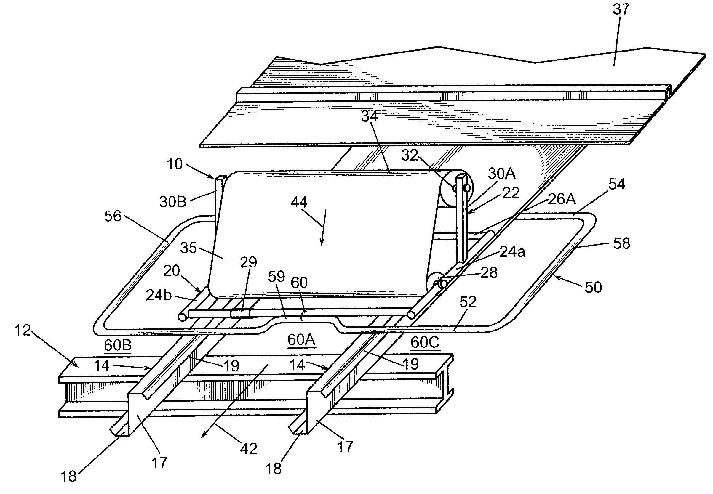
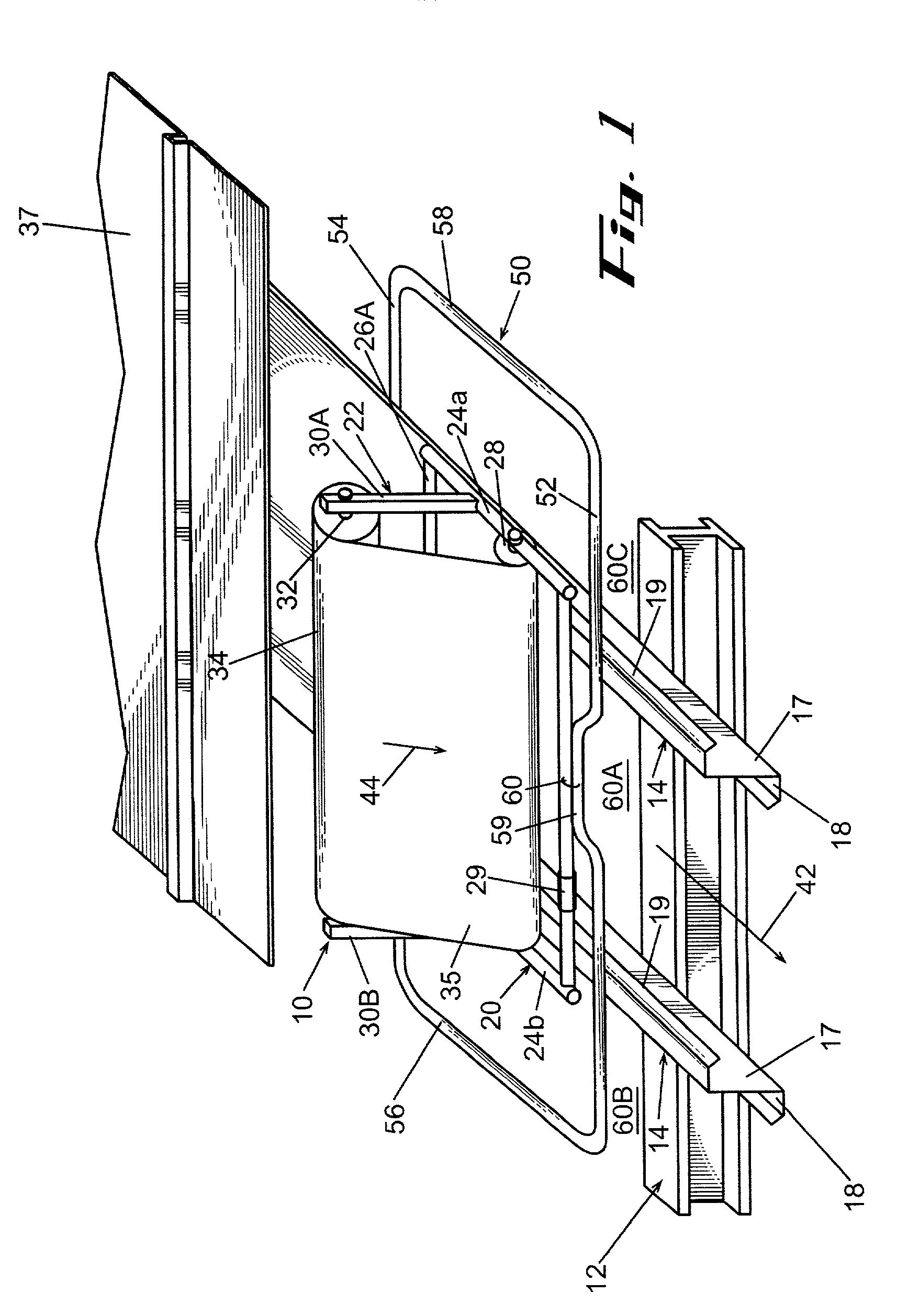
[0032]Referring now in more detail to the drawings, in which like numerals indicate like parts throughout the several views, FIG. 1 is a perspective illustration of a roof insulation support carriage 10 mounted on a conventional, partially completed roof of an industrial building. The roof includes a plurality of parallel, inclined rafters 12 (only one shown) and a plurality of parallel, horizontally extending purlins, such as the pair of purlins 14 and 16. Each purlin includes a central web 17 and lower and upper oppositely facing flanges 18 and 19.

[0033]The roof insulation support carriage 10 includes a rectangular support frame 20 and a vertical reel support 22 mounted on and extending upwardly from the frame. The support frame 20 includes longitudinally extending side bars 24A and 24B and laterally extending cross bars 26A and 26B that form the rectangular shape of the support frame, and cross roller 28 that is rotatably supported by its axle to side bars 24A and 24B. The suppor...


PUM


Abstract

A plurality of sheet supports 50 or 70 of approximate rectangular configuration are placed on adjacent purlins 14 of a partially completed roof of an industrial building, about the second row of roof insulation support carriages 10. When the carriages are advanced along the lengths of the purlins to apply the sheet material 34 to the purlins, the sheet supports 50 or 70 move in unison with the carriages of the second row of carriages and the rear segment 54 supports the sheet material in the spaces 60 over which the carriage is mounted and the side segments 56 and 58 support the sheet material extending from the first row of carriages in the next adjacent spaces between the purlins. This avoids the sagging of the sheet material between the purlins at the time when the hard roof panels 37 are fastened to the purlins.

Description

CROSS REFERENCE TO RELATED APPLICATION[0001]This is a continuation-in-part of U.S. patent application Ser. No. 10 / 096,119, filed Mar. 8, 2002 now U.S. Pat. No. 6,672,024.FIELD OF THE INVENTION[0002]This invention relates to the progressive application of flexible sheet material, such as blanket insulation, to the purlins of a roof during the progressive construction of a roof of an industrial building. More particularly, the invention involves a plurality of carriages for carrying reels of flexible sheet material in two rows of carriages along adjacent purlins of a roof and dispensing the sheet material onto the purlins in response to the movement of the carriages.BACKGROUND OF THE INVENTION[0003]Industrial buildings have roof structures that typically include inclined rafter beams that extend parallel to each other and are sloped from the eaves up to the ridge of the building structure. Horizontally oriented purlins are mounted on the rafters and extend parallel to each other in a ...

Claims


Application Information

Patent Timeline
IPC IPC(8): E04F21/00E04D15/00E04F21/18E04D15/06
CPCE04D15/06E04F21/00E04F21/18E04F21/1861
Inventor ALDERMAN, ROBERT J.
Owner ALDERMAN ROBERT J
Learn More