Inhaler device

a technology of inhaler device and inhaler body, which is applied in the field of medicine inhalers, can solve the problems of not providing the user with information about the effectiveness of self-administered doses, the type does not provide the user with information about whether or not, and the user may have difficulty in using the type of inhaler device with repetitive accuracy, etc., to achieve the effect of reducing pressur

Inactive Publication Date: 2005-10-18
KHAN KHAJA H
View PDF11 Cites 18 Cited by
  • Summary
  • Abstract
  • Description
  • Claims
  • Application Information

AI Technical Summary

Benefits of technology

[0011]An object of the claimed invention is to provide an improved inhaler device that provides the users with readily viewable feedback of the user's inhalation progress.
[0012]Another object of the claimed invention is to provide an improved inhaler device that provides an unobstructed view of the activity in the inhaler device.
[0014]An even further object of the claimed invention is to provide an improved inhaler device with a float indicator interacting with the inhalation of the medicinal mist to provide a user of the device with accurate, readily viewable feedback of the progress of the user's inhalation.
[0017]At least one inlet aperture through an outer wall of the minor cavity below the float indicator seat maintains pressure within the minor cavity below the float indicator substantially equal to ambient pressure outside of the body. The float indicator seat prevents the float indicator from obstructing the inlet aperture.
[0018]A mouth piece in communication with the interior of the body by way of a one way valve within an outer wall of the body is located such that inhalation through the mouth piece reduces the pressure within the major cavity and within the minor cavity above the float indicator. The reduction in pressure within the major cavity and minor cavity draws the medicinal fluid through the one way valve and mouthpiece and creates a pressure difference across the float indicator. The pressure difference across the float indicator causes the float indicator to move toward the inhaler top, the transparency of the body allowing visualization of the float indicator moving toward the inhaler top as the medicinal fluid moves from the major cavity and through the one way valve and mouthpiece into the user's mouth.

Problems solved by technology

Inhaler devices of this type do not provide the user with information about the effectiveness of a self-administered dose and coincidentally does not alert the person using the device as to whether he or she is using the inhaler device properly.
Further, younger users may have difficulty in using an inhaler device of this type with repetitive accuracy.
However, this device does not provide the user with information concerning whether or not the mist delivered by the medicine canister was properly received by the user.
As a consequence, the medicine canister partial blocks the view of the indicator tube preventing the user from fully viewing the activity in the indicator tube.
Even further, the Dwork device does not provide indicia of the amount of force the user is using to draw the medicinal mist into the user's lungs other than the indication that the user has inhaled with an amount of force to bring the ball within the indicator tube to stop at the top of the indicator tube.
The inhalation device allows the user to view the activity inside the device but does not provide the user with readily viewable indicia of the dosage progress.

Method used


Image

  • Inhaler device
  • Inhaler device

Examples


Embodiment Construction

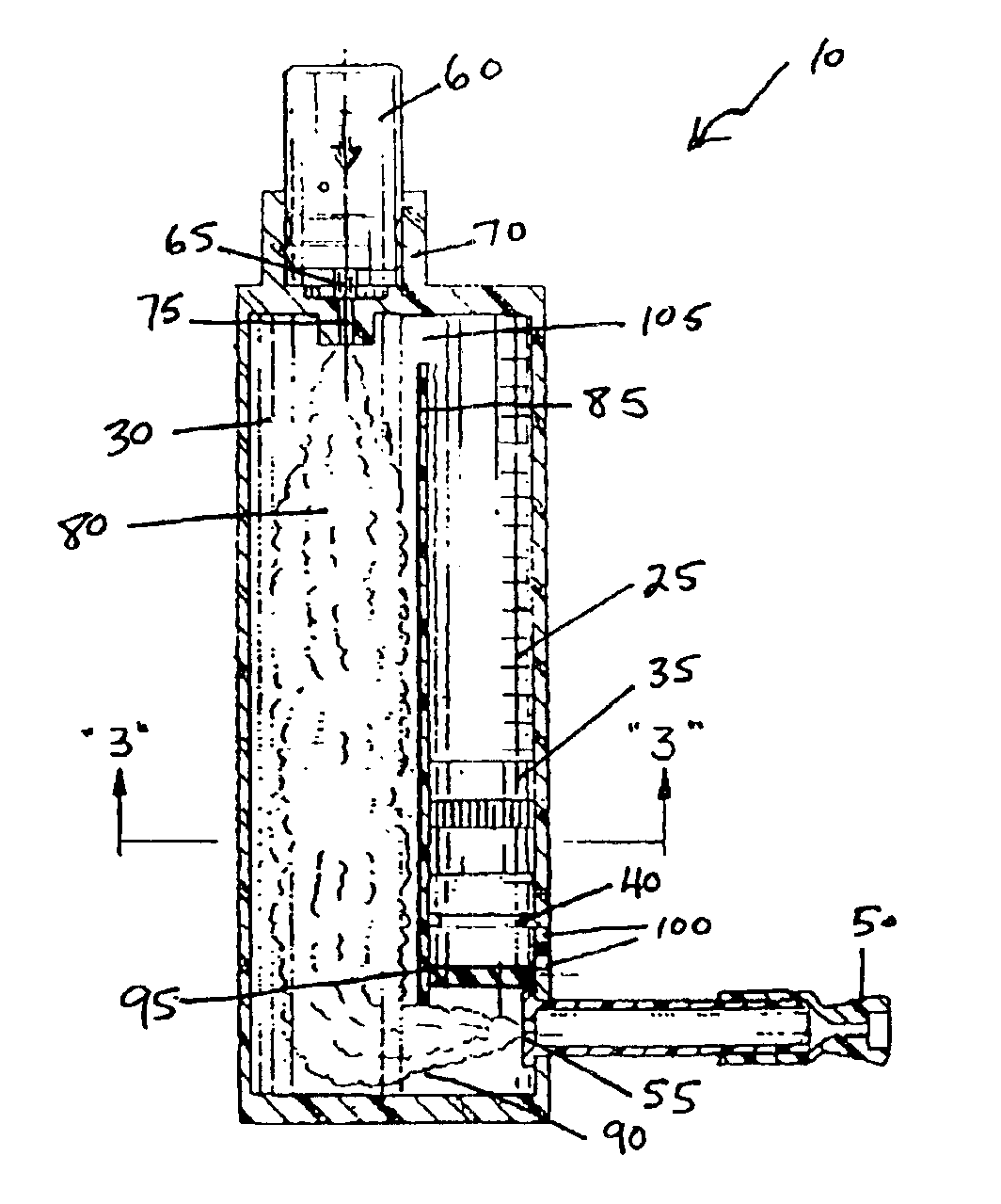
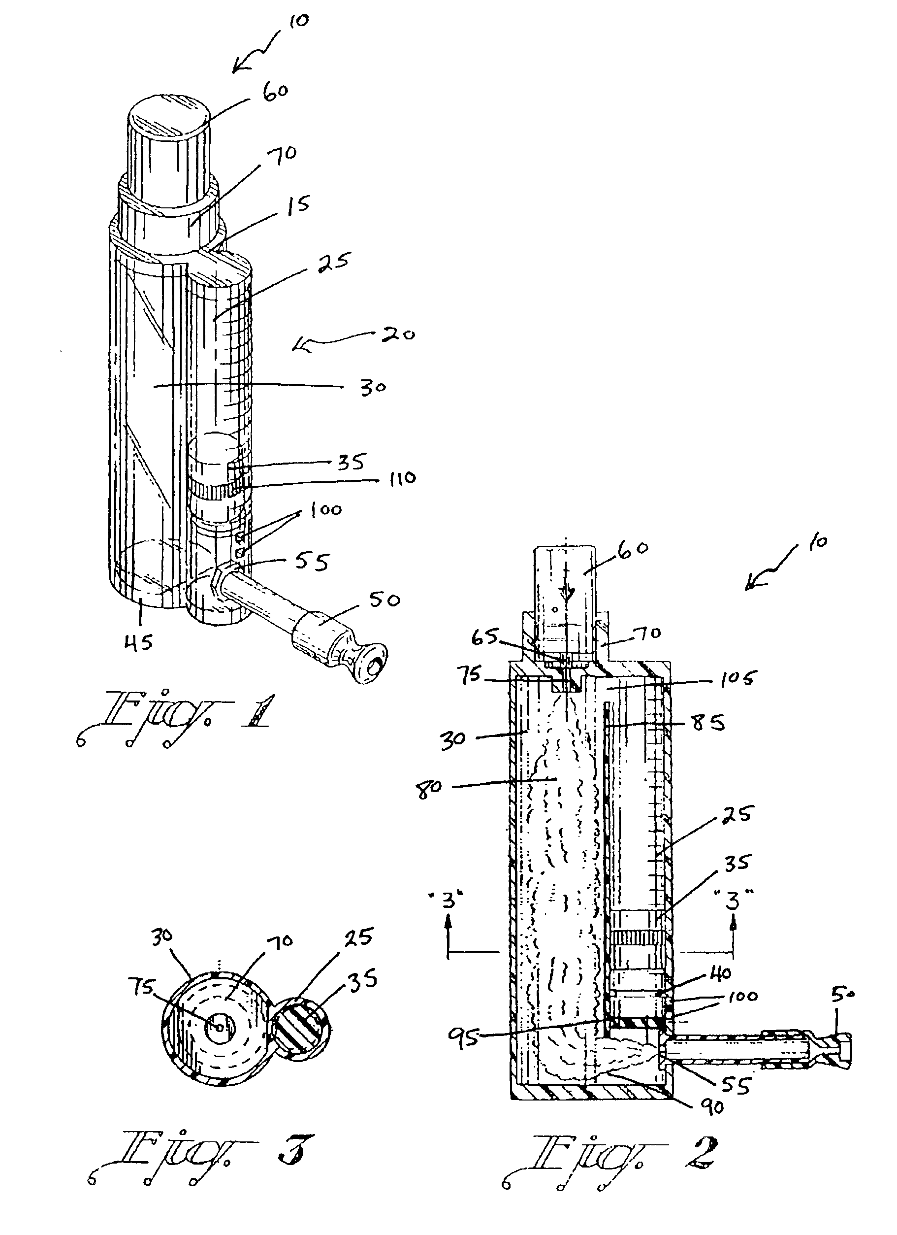
[0022]FIGS. 1-3 show an embodiment of the inhaler device 10. The inhaler device as shown in FIGS. 1-3 is used in an upright fashion to provide an unobstructed view of the activity in the inhaler device 10 during use. The inhaler device 10 generally consists of an inhaler top 15, an inhaler body 20 having a minor cavity 25 and a major cavity 30, a float indicator 35 and float indicator seat 40, an inhaler bottom 45, and a mouthpiece 50 connected to the body 20 by a one way valve 55. A medicine canister 60 can be placed in the inhaler device 10 as shown.

[0023]The medicine canister 60 as shown in FIGS. 1 and 2 is a standard canister having a nozzle 65 that dispenses the medicinal mist 80 from the medicine canister 60. The inhaler device 10 as shown in FIGS. 1-3 is designed to accept this standard sized canister 60, however it is within the scope of the invention that the inhaler device 10 could be designed to accept canisters of other sizes.

[0024]FIGS. 1 and 2 show the inhaler top 15 i...


PUM

PropertyMeasurementUnit
heightaaaaaaaaaa
diameteraaaaaaaaaa
diameteraaaaaaaaaa

Abstract

A device used with fluid canisters comprising a transparent body allowing the viewing of movement within the body having a minor and major cavity with a float indicator and float seat within the minor cavity. An inhaler top and bottom fits each end of the body forming an airtight chamber within the major and minor cavity above the float, the top having a seat to accept a canister and a nozzle aperture to accept a nozzle of the canister oriented to release fluid from the canister into the major cavity. An inlet through the minor cavity below the seat maintains pressure equal to pressure outside of the body within the minor cavity. Inhalation through a mouthpiece and one way valve reduces pressure within the major and minor cavity above the float drawing fluid through the one way valve creating a pressure difference across the float causing it to move.

Description

BACKGROUND OF THE INVENTION[0001]1. Field of the Invention[0002]The present invention generally relates to medicine inhalers. More specifically, the present invention relates to medicine inhalers having structure for viewing the inhalation of medicine.[0003]2. Description of the Prior Art[0004]Persons with respiratory ailments such as asthma or emphysema commonly use prescription drugs such as Albuterol to treat their aliment. Drugs of this type are generally made in liquid form and are stored in small medicine canisters. The medicine canisters generally have a nozzle within one end to release the liquid in the form of a mist. The mist is then inhaled into the lungs to medicate the user of the drug.[0005]The medicine canister is typically used by placing the canister into an inhaler device that facilitates the transferal of the medicinal mist to the user's lungs. A typical inhaler device consists of a housing for receiving the canister, a seat portion with passage for directing the ...

Claims


Application Information

Patent Timeline
Patent Type & Authority Patents(United States)
IPC IPC(8): A61B5/087A61B5/08A61M15/00
CPCA61B5/0876A61M15/0086A61M15/009A61M2205/583
Inventor KHAN, KHAJA H.
Owner KHAN KHAJA H
Why Eureka
Try Eureka