Structure for illuminating pointer of meter

Inactive Publication Date: 2005-10-18
CALSONIC KANSEI CORP
View PDF8 Cites 30 Cited by
  • Summary
  • Abstract
  • Description
  • Claims
  • Application Information

AI Technical Summary

Benefits of technology

[0010]It is, therefore, an object of the present invention to provide a structure for illuminating a pointer of a meter, which

Problems solved by technology

Although the hot stamp 10 is provided on the upper surface 6a of the pointer body 6 so that functional parts of the scattering member 9 and so on within the po

Method used


Image

  • Structure for illuminating pointer of meter
  • Structure for illuminating pointer of meter
  • Structure for illuminating pointer of meter

Examples


Example

[0022]Several embodiments of the present invention will be explained with reference to FIGS. 1 to 7 below. In FIGS. 1 to 7, the same references numerals are attached to parts similar to that as in the prior art as described above.

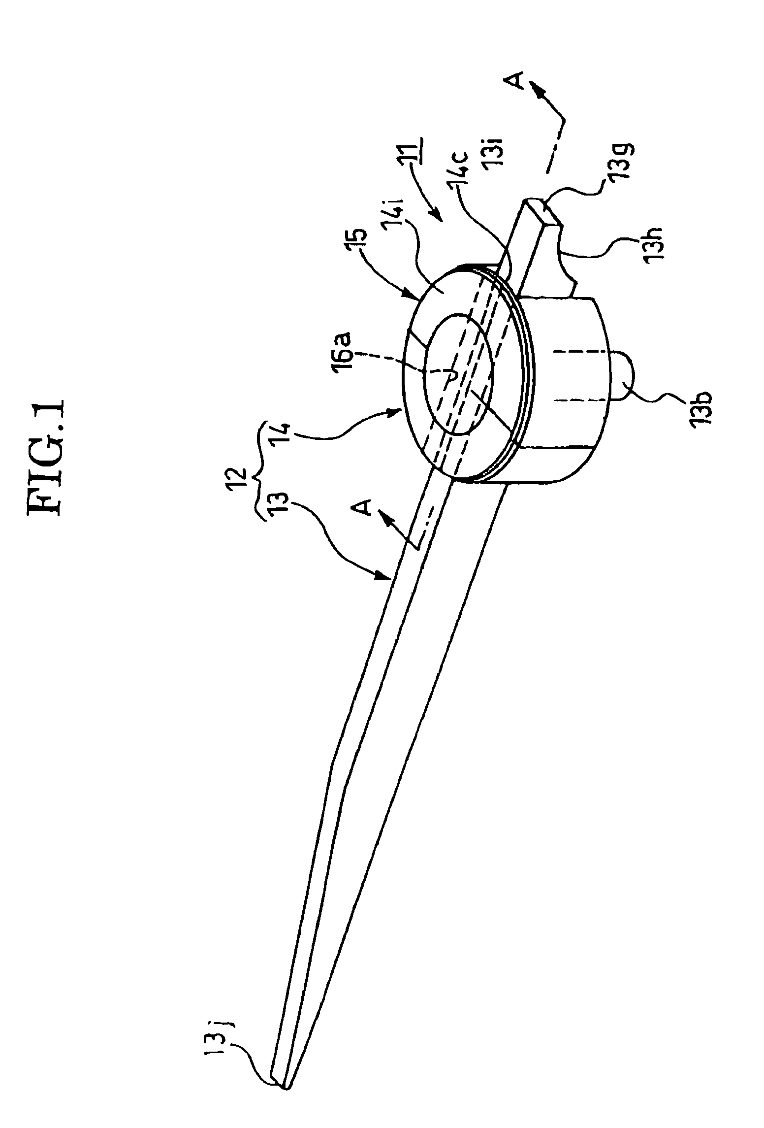
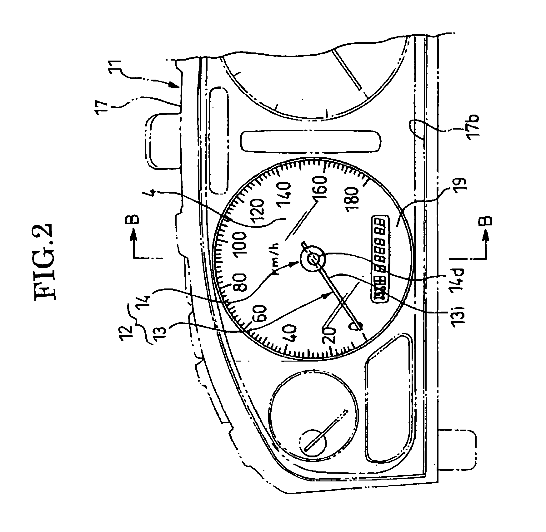
[0023]FIGS. 1 to 3 illustrate on embodiment of a structure for illuminating a pointer of a meter, according to the present invention.

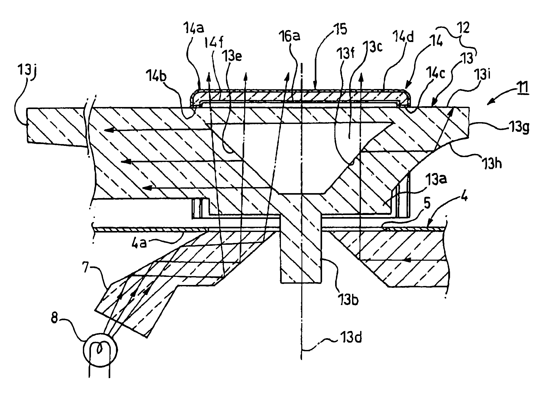
[0024]The structure for illuminating the pointer of the meter, in the embodiment comprises a pointer 12 provided in the meter 11 for a vehicle and a cover cap member 14 provided on the pointer 12.

[0025]The pointer 12 is formed of a light translucent material and includes an elongated pointer body 13. The pointer body 13 has a disk shaped base 13a integrally formed with the pointer body 13. An upper surface of the base 13a is provided with a light emitting surface 13i. The cover cap member 14 is disposed to cover a portion of the light emitting surface 13i and fixed to the base 13a by any suitable means.

[0026]A lower surface of...


PUM


Abstract

A structure for illuminating a pointer of a meter, including a light translucent pointer including a pointer body having a base provided with a light emitting surface, and a cover cap member provided on said light emitting surface of the base, the pointer body including a reflective/refractive plane provided in said base, the reflective/refractive surface reflecting a portion of illumination light introduced in the base to go longitudinally of the pointer body and transmitting another portion of the illumination light to go toward the light emitting surface, the cover cap member having a light translucent layer and a light shielding layer disposed inside the light translucent layer, the light shielding layer having an opening passing through the another portion of the illumination light transmitting the reflective/refractive plane.

Description

BACKGROUND OF THE INVENTION[0001]1. Field of the Invention[0002]The present invention relates to a structure for illuminating a pointer of a meter, installed in a meter device or the like for a vehicle, particularly to a structure for illuminating a pointer of a meter, which is easy to look the pointer throughout the daytime and the nighttime.[0003]2. Description of Related Art[0004]Conventionally, there is known a structure for illuminating a pointer of a meter in a meter device mounted on a vehicle such as an automobile or the like as shown in FIG. 8 (for example, see FIG. 1, Japanese Utility Model Publication H 6-7310).[0005]In the conventional structure for illuminating the pointer of the meter, the pointer 2 of the meter 1 for the vehicle has a rotating shaft 3, which is inserted rotatably into an opening 5 formed in a dial 4, as shown in FIG. 8.[0006]The pointer 2 has a pointer body 6 made of a translucent material. The dial 4 is located below the pointer 2, and a light guidin...

Claims


Application Information

Patent Timeline
IPC IPC(8): F21V33/00G01D13/22G01D13/00G01D11/28G01D13/28G01D13/26
CPCG01D11/28G01D13/265B60K2370/6992
Inventor ISHII, MIKIO
Owner CALSONIC KANSEI CORP
Why Eureka
Try Eureka