Clean room system

a clean room and structure technology, applied in the space field, can solve the problems of large contaminants, particle contamination, and large contamination of particles coming from staff and clean facilities, and achieve the effect of effectively utilizing a spa

Inactive Publication Date: 2005-10-18
LG DISPLAY CO LTD
View PDF0 Cites 142 Cited by
  • Summary
  • Abstract
  • Description
  • Claims
  • Application Information

AI Technical Summary

Benefits of technology

[0013]Another object of the present invention is to provide a clean room system capable of effectively utilizing a space.

Problems solved by technology

The liquid crystal display device formed by such a process can easily become defective due to fine dust or particle generated during the process.
Staff, equipment, facility (including clean room), and chemicals are a major cause of fine particle contamination.
Especially, particles coming from staff and the clean facility are major contaminants.

Method used


Image

  • Clean room system
  • Clean room system
  • Clean room system

Examples


Embodiment Construction

[0028]Reference will now be made in detail to the preferred embodiments of the present invention, examples of which are illustrated in the accompanying drawings.

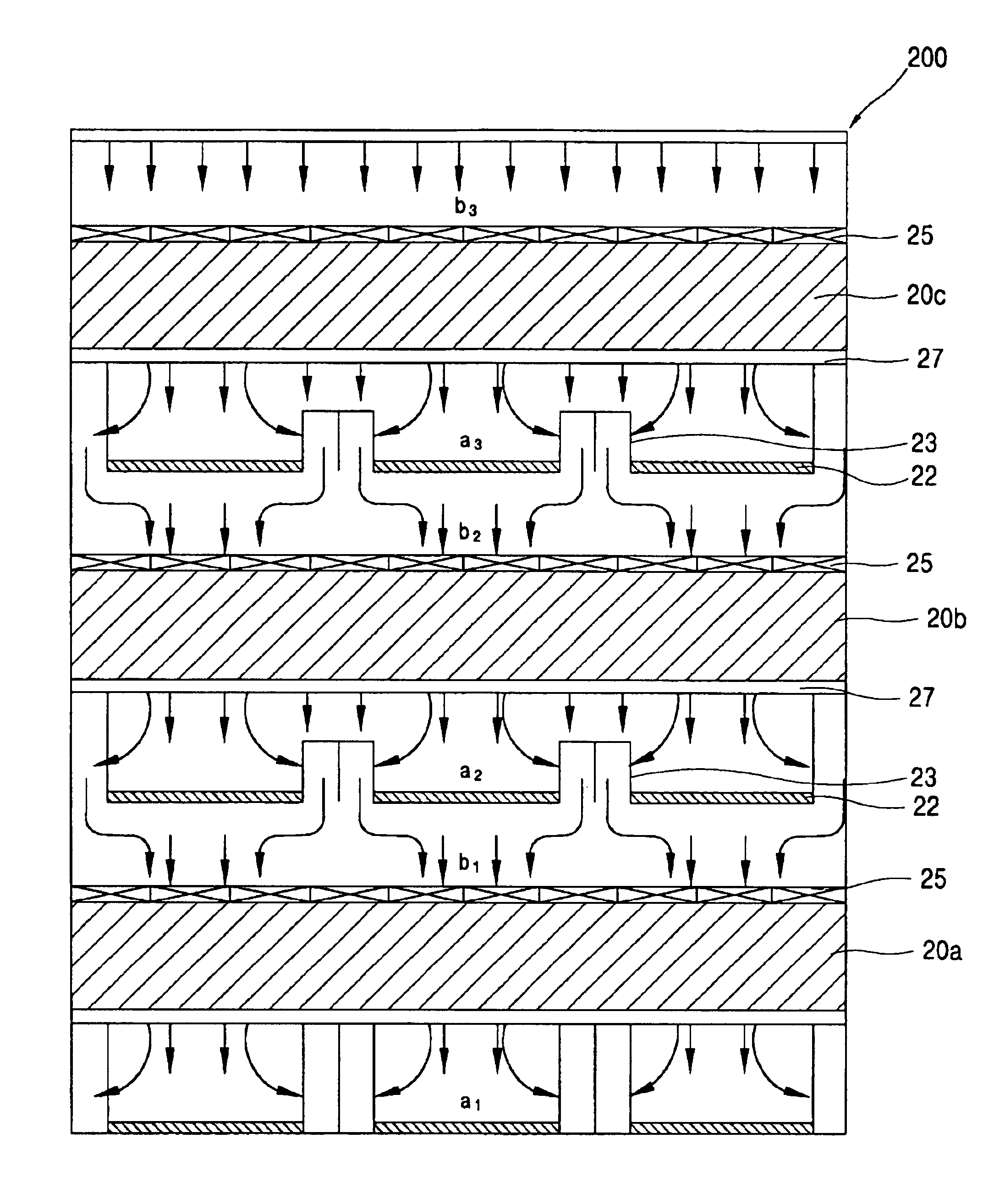
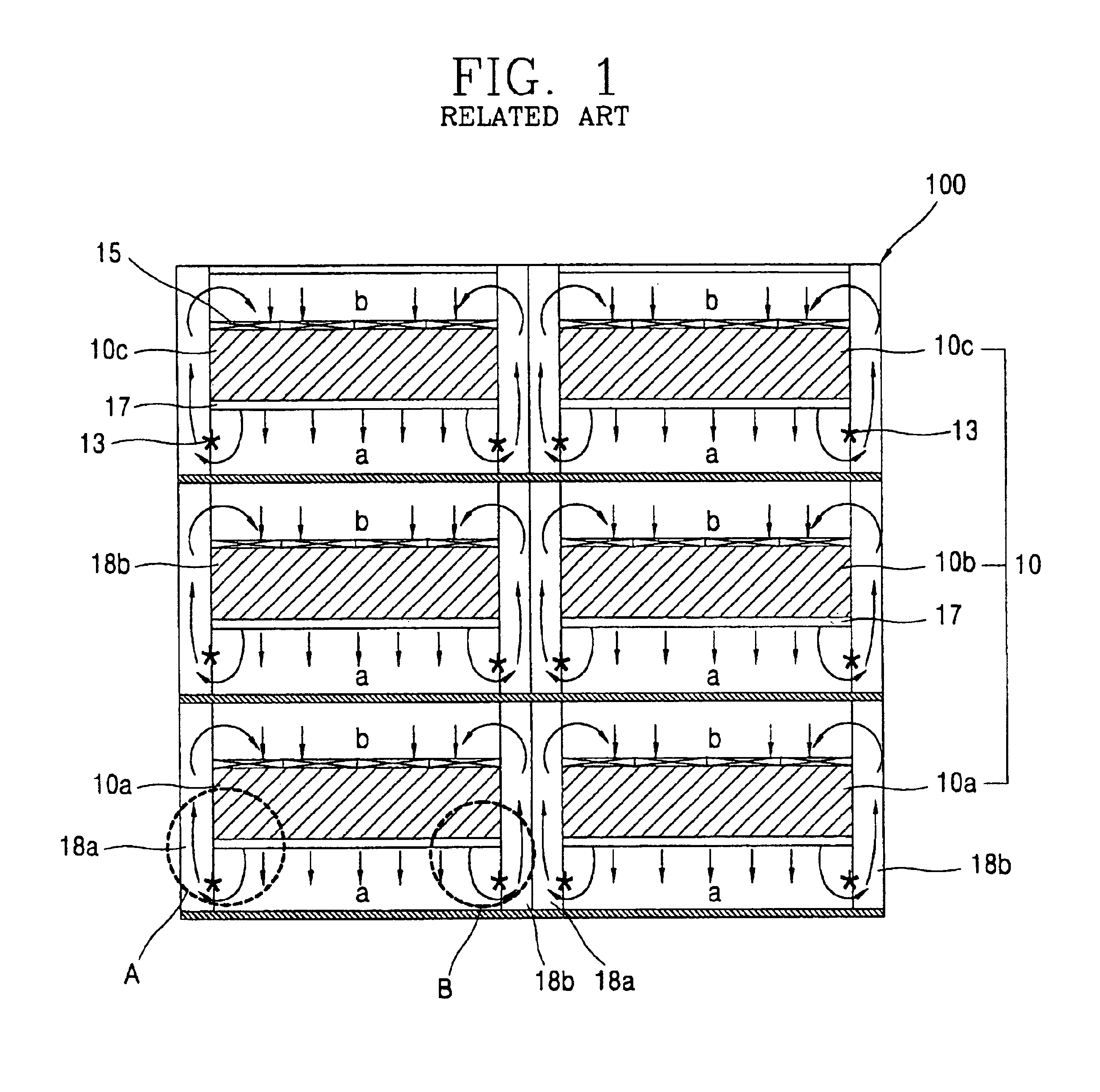
[0029]FIG. 3 is a sectional view showing the construction of a clean room system in accordance with the present invention. The clean room system of FIG. 3 shows a three-story clean room system that is compared to the related art clean room system.

[0030]As shown in FIG. 3, a clean room system 200 includes a plurality of multi-level clean rooms 20a-20c in which a fabrication process such as a deposition or an etching is performed, lower and upper spaces a1-a3 and b1-b3 provided at lower and upper sides of the clean rooms 20a-20c and supplying and discharging an air stream; and a fan filter unit 25 disposed at the ceiling of each clean room 20a-20c and generating a vertical air stream between the upper clean room and the lower clean room.

[0031]Dry coils 23 are provided at the interlayer boundary plate 22 discriminating levels o...


PUM


Abstract

A clean room system is provided. The clean room includes a plurality of multi-level clean rooms and an air passage. The plurality of multi-level clean rooms has at least a lower clean room and an upper clean room above the lower clean room. The air passage permits air flow between the upper clean room and the lower clean room and smooths the air flow.

Description

[0001]The present application claims the benefit of Korean Patent Application No. 2003-42960 filed in Korea on Jun. 28, 2003, which is hereby incorporated by reference.BACKGROUND OF THE INVENTION[0002]1. Field of the Invention[0003]The present invention relates to a space for fabricating a semiconductor device or a liquid crystal display device, and more particularly, to a structure of a clean room system having improved uniformity of air flow in a substantially vertical direction within a fabrication space.[0004]2. Description of the Related Art[0005]Development of TFT-LCD technology and its application have been accelerated with increased size and resolution. Presently, growth of productivity and low price are important factors for a product. To achieve this, cooperation between manufacturers, related material industries and fabrication equipment providers is required for simplification of the fabrication process and improvement in yield.[0006]The fabrication process of a TFT-LCD ...

Claims


Application Information

Patent Timeline
Patent Type & Authority Patents(United States)
IPC IPC(8): F24F3/16H01L21/02
CPCF24F3/161Y10S414/135F24F3/167H01L21/02
Inventor KIM, DONG-HAN
Owner LG DISPLAY CO LTD
Why Eureka
Try Eureka