

Adjustable step trainer
a step trainer and adjustable technology, applied in the field of adjustable step trainers, can solve the problems of difficult user loosening and pulling out the straps, inaccurate step range, and troublesome adjustment, and achieve the effect of convenient use of the step trainer and easy adjustment of the slat position
- Summary
- Abstract
- Description
- Claims
- Application Information
AI Technical Summary
Benefits of technology
Problems solved by technology
Method used
Image

Examples
first embodiment
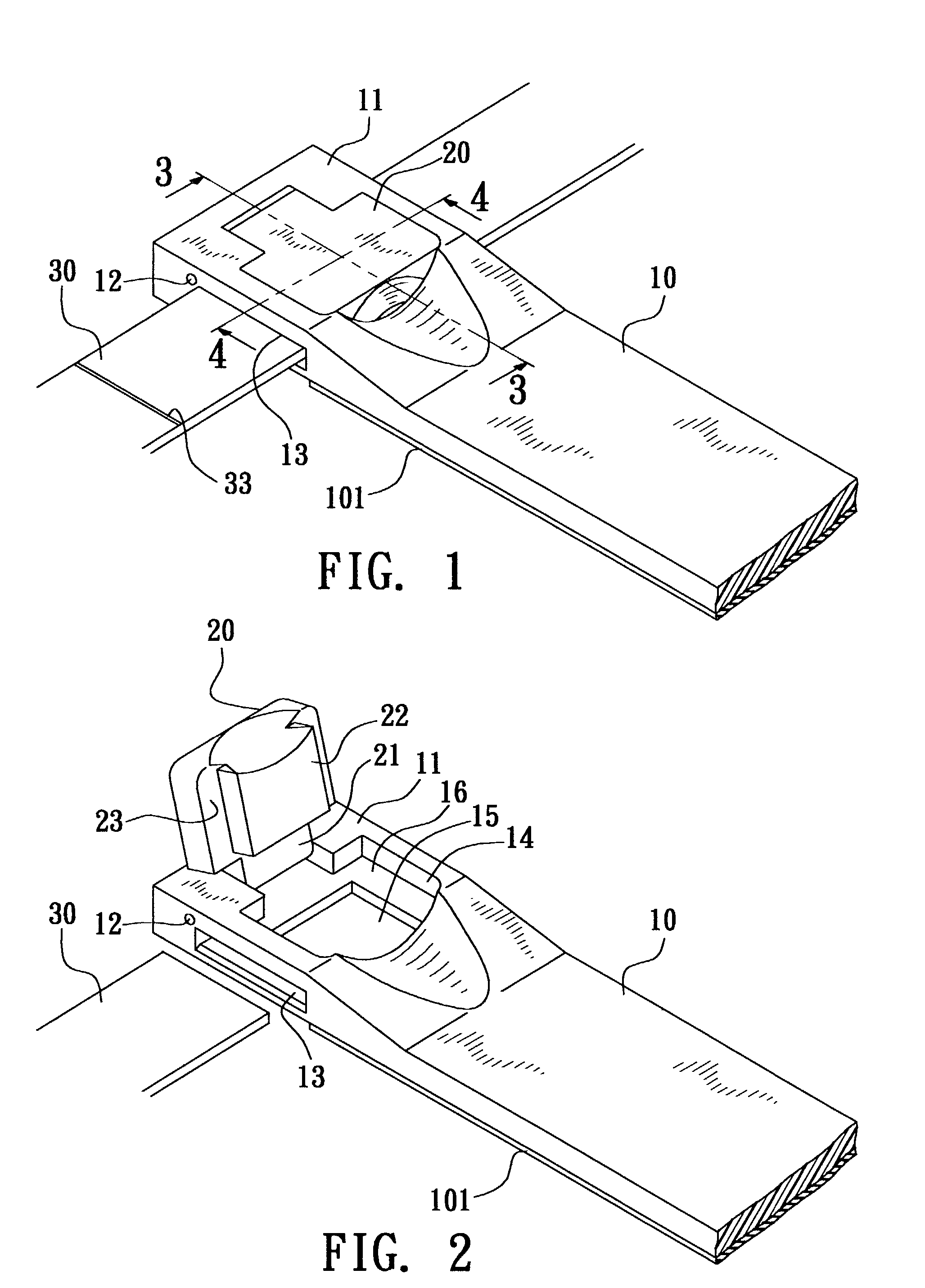
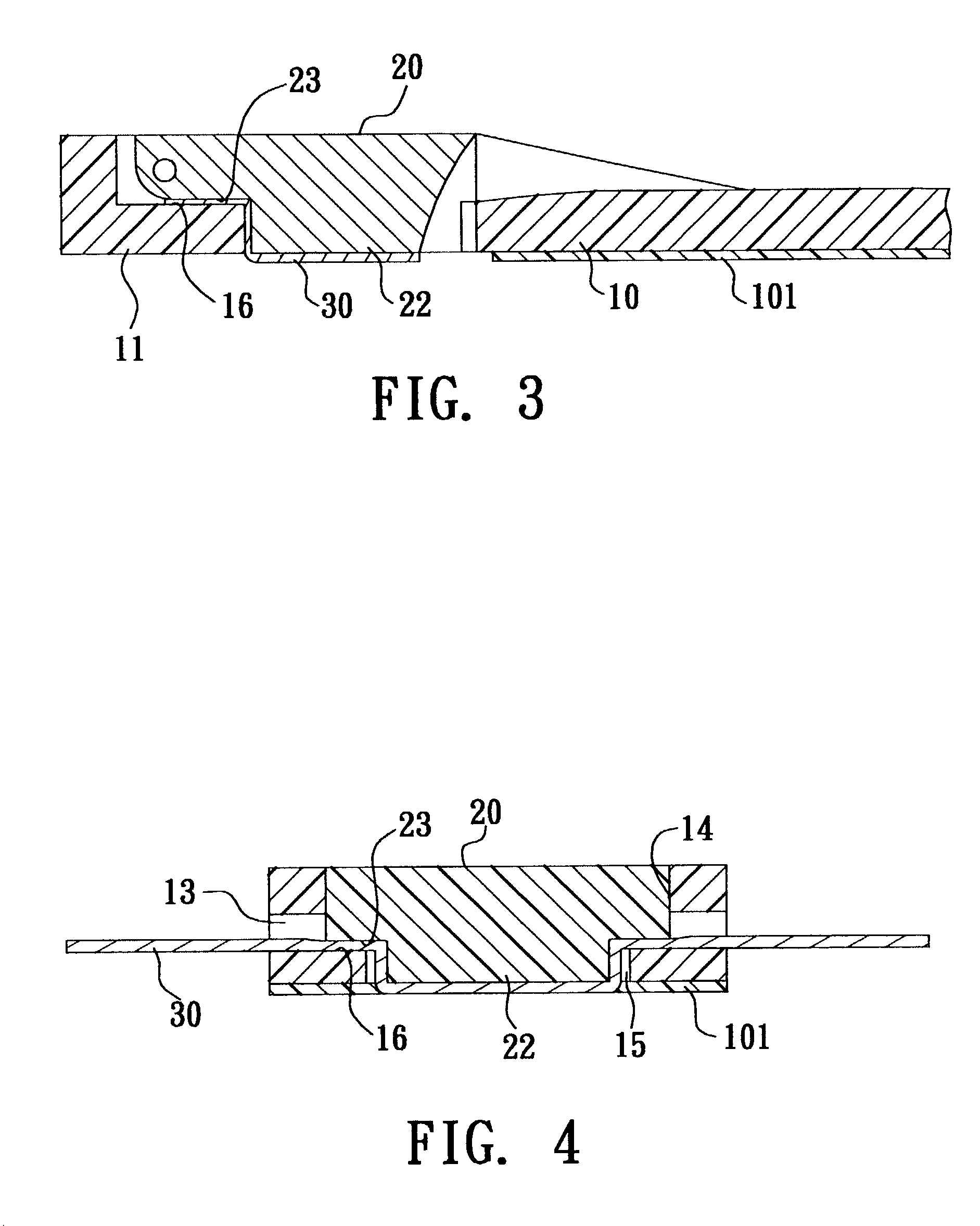
[0031]Please refer to FIGS. 1 to 6. the adjustable step trainer of the present invention includes two straps 30 and more than one slat 10 through which the straps 30 are passed.
[0032]The slat 10 is an elongated member having two fixing sections 11 at two ends. One side of the fixing section 11 has a pivot section 12. In this embodiment, the pivot section 12 is a hole formed on two sides of the fixing section 11. The fixing section 11 further has a through section 13 horizontally longitudinally passing through the fixing section 11. The through section 13 is longitudinally formed with a first recess 14. A second recess 15 is further formed under the bottom of the first recess 14. The second recess 15 has a cross-sectional area smaller than that of the first recess 14. The fixing section 11 is formed with a top face 16 at the adjoining sections of the first and second recesses 14, 15. In addition, the middle section of the slat 10 is formed with an insertion through hole 17. The inse...
second embodiment
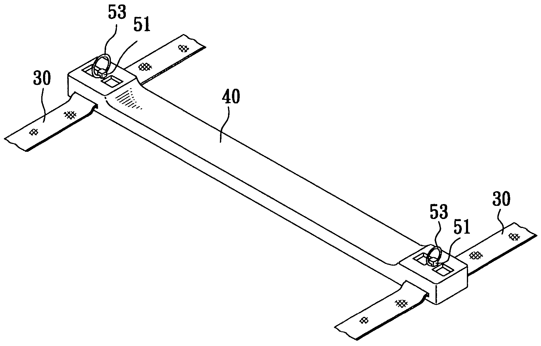
[0039]FIGS. 7 to 11 show the present invention, in which the fixing section at each end of the slat 40 is formed with a receiving section 41 having an opening facing downward. The center of top face of the receiving section 41 is formed with a square through hole 411. Two sides of the receiving section 41 are formed with horizontal longitudinal slots 412 near the bottom edge thereof. The strap 30 is passed through the slots 412.
[0040]In this embodiment, the press unit is a press board 50 having a shape adapted to the receiving section 41. A column 51 is disposed on the press board 50. In this embodiment, the column 51 has a square shape or other shape adapted to the through hole 411 of the receiving section 41 for preventing the column 51 from rotating. A certain portion of the column 51 is formed with a through hole 511. A resilient member such as a spring 52 is fitted on the column 51. The press board 50 is mounted in the receiving section 41 of the slat 40 with the column 51 exte...
third embodiment
[0045]FIGS. 12 to 16 show the present invention, in which a fixing section 61 is disposed at each end of the slat 60. The fixing section 61 is formed with a chamber 62 having an opening facing downward. The fixing section 61 is formed with a horizontal longitudinal through section 63 passing through the chamber 62 near the bottom edge of the fixing section 61. The strap 30 is passed through the through section 63. A stop bar 64 is transversely disposed in the chamber 62. A through hole 65 is transversely formed on the fixing section 61 above the stop bar 64.
[0046]In this embodiment, the press unit is a snap member 70. One end of the snap member 70 is formed with a detent section 71 such as a pawl or an embossed section. The lower face of the snap member 70 has two projecting sections 72 spaced by a certain distance. Each projecting section 72 has a hole 721. A resilient member such as a spring 73 is disposed between the two projecting sections 72. A bolt 74 is passed through the thr...
PUM
 Abstract
Description
Claims
Application Information