Image display apparatus, image display method, measurement apparatus, measurement method, information processing method, information processing apparatus, and identification method

a technology of image display and image display method, which is applied in the direction of liquid/fluent solid measurement, navigation instruments, nuclear elements, etc., can solve the problems of not describing any practical registration method required, information is not easily recognized intuitively, and the movable range of the observer is limited,

Active Publication Date: 2005-10-18
CANON KK
View PDF8 Cites 44 Cited by
  • Summary
  • Abstract
  • Description
  • Claims
  • Application Information

AI Technical Summary

Benefits of technology

[0064]wherein when said determination unit determines that the process for calculating the coordinate position of the index of interest on the sensed image by the first calculation unit is to be executed, the process for determining correspondence b

Problems solved by technology

With the conventional car navigation system, the driver must associate navigation information (normally superposed on a map) presented on the display with the real scene by himself or herself, and such information is not easily recognized intuitively.
However, this reference does not describe any practical registration method required to present navigation information to be superimposed at an appropriate position on the real scene.
However, since a magnetism or ultrasonic wave source must be arranged in the real scene, the movable range of the observer is limited.
Also, such method cannot obtain sufficiently high measurement precision.
However, the registration method in the aforementioned mixed reality presentation apparatus using the HMD cannot realize registration in the On-the-Scene HUD.
Since the method described in non-patent ref

Method used


Image

  • Image display apparatus, image display method, measurement apparatus, measurement method, information processing method, information processing apparatus, and identification method
  • Image display apparatus, image display method, measurement apparatus, measurement method, information processing method, information processing apparatus, and identification method
  • Image display apparatus, image display method, measurement apparatus, measurement method, information processing method, information processing apparatus, and identification method

Examples


first embodiment

[First Embodiment]

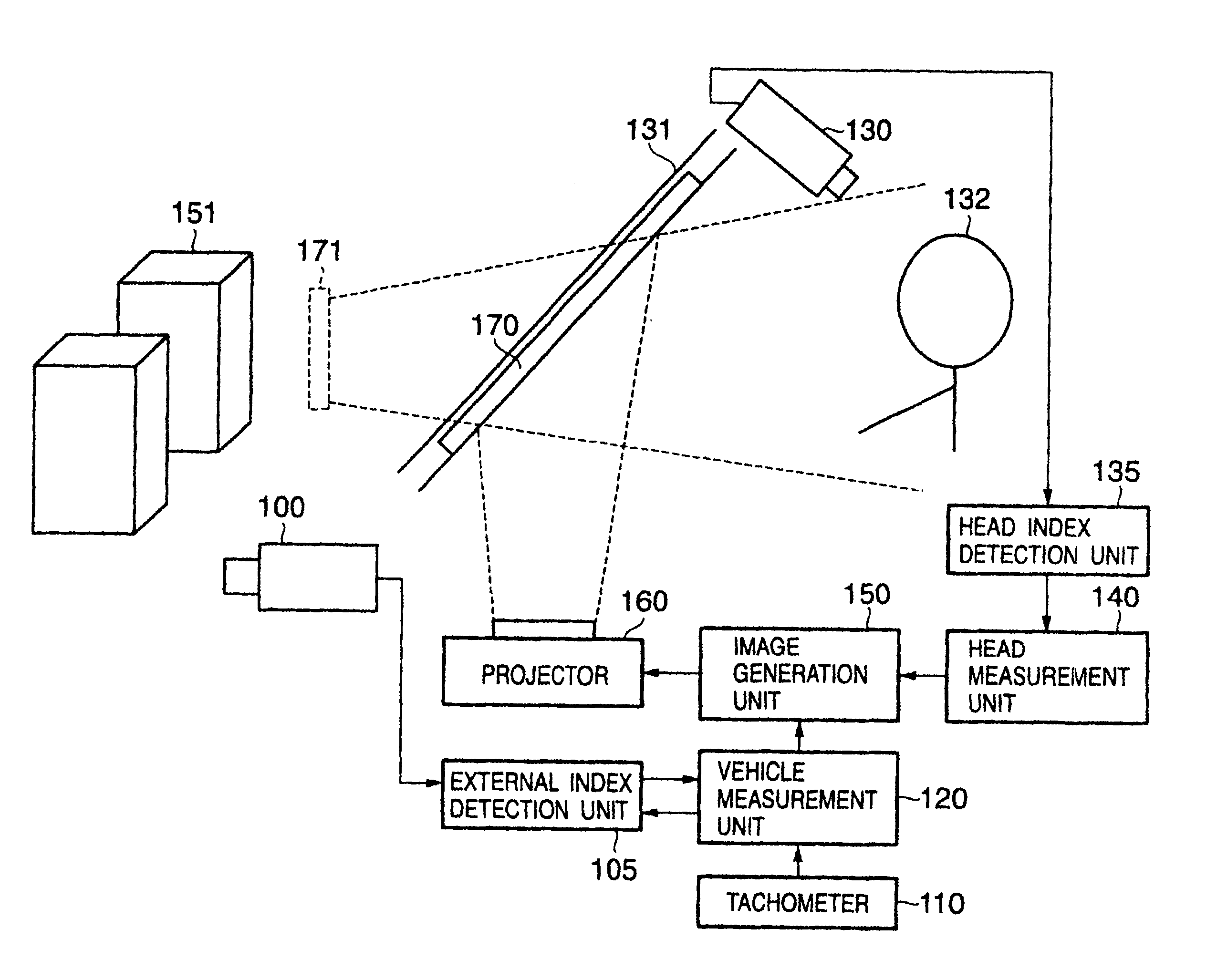
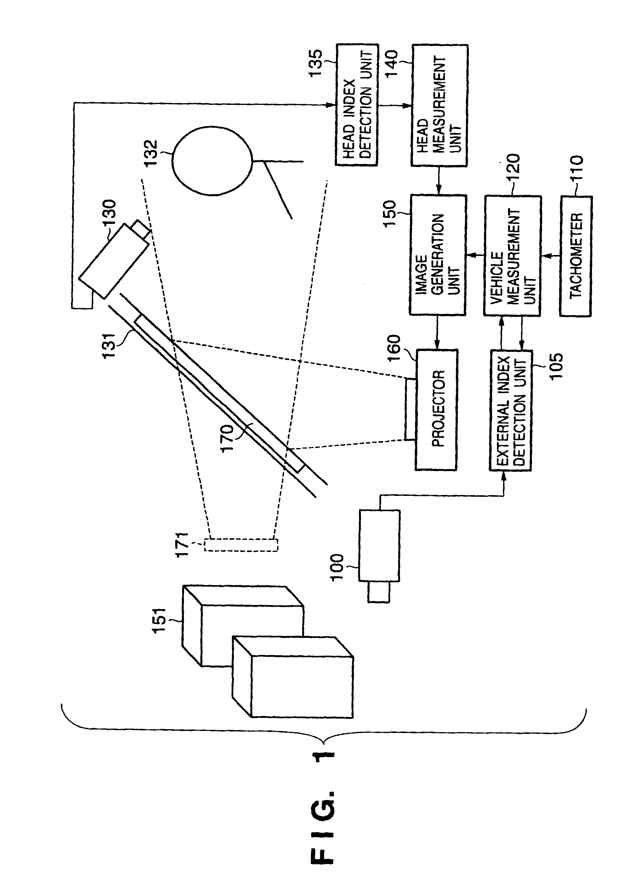
[0112]FIG. 1 is a block diagram showing the functional arrangement of an image display apparatus according to this embodiment, which is mounted on a vehicle. The image display apparatus of this embodiment comprises an external image sensing camera 100, external index detection unit 105, tachometer 110, vehicle measurement unit 120, passenger image sensing camera 130, head index detection unit 135, head measurement unit 140, image generation unit 150, projector 160, and combiner 170.

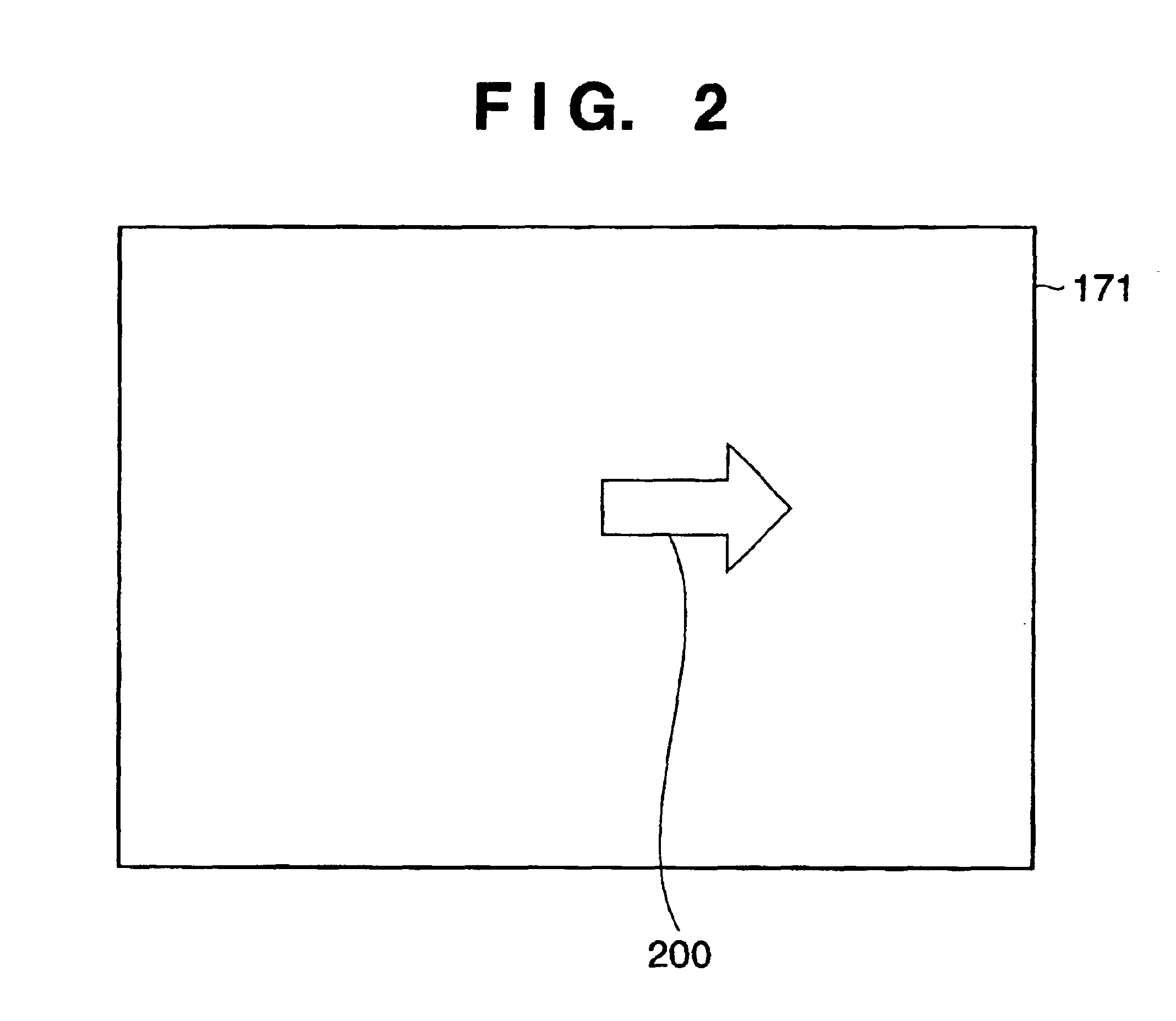
[0113]A passenger 132 of the vehicle (in this embodiment, the passenger is also a driver of the vehicle) can visually observe an object 151 of an external world via a front windshield portion 131, and can also visually observe an image indicating navigation information which is displayed on the combiner 170 attached to the front windshield portion 131 and is generated by a process to be described later of the image display apparatus. That is, the passenger 132 can visually observe the na...

second embodiment

[Second Embodiment]

[0203]In the above embodiment, the vehicle measurement unit 120 defines state equation fk(xk) using equation (2). Since equation (2) is the state equation based on a model that allows the vehicle to freely pitch and roll, the estimated value of the position of the vehicle obtained using this equation is often largely different from an actual value. This embodiment introduces a nonholonomic constraint based on the assumption that the vehicle never skids, and sets, in place of equation (2), state equation fk(xk) which is improved as: fk⁡(xk)=[xw  b⁡(tk)+xw′ b⁡(tk)·Δ⁢ ⁢tyw  b⁡(tk)+yw′ b⁡(tk)·Δ⁢ ⁢tζw  b⁡(tk)+ζw′ b⁡(tk)·Δ⁢ ⁢txw′ b⁡(tk)-vk·ζw′ b⁡(tk)·Δ⁢ ⁢t·cos⁢ ⁢ζw   ⁢b⁡(tk)yw′ b⁡(tk)-vk·ζw′ b⁡(tk)·Δ⁢ ⁢t·sin⁢ ⁢ζw   ⁢b⁡(tk)ζw′ b⁡(tk)]T(18)

[0204]Note that the above equation merely considers a nonholonomic constraint in estimation of the state vector, and the dimensions themselves of the state vector do not degenerate. Thus, by importing appropriate system noise characteri...

third embodiment

[Third Embodiment]

[0205]The tachometer 110 in the above embodiment measures the rotational velocity of the wheel using the rotary encoder. However, the arrangement of the tachometer 110 is not limited to such specific one, and any other arrangements may be adopted as long as the rotational velocity of the wheel can be measured. For example, pulse sensors attached to the two rear wheels for the purpose of, e.g., orientation control of the vehicle may be used as the tachometer 110. In this embodiment, the diameter of the rear wheel 500 can be used as the value B in equation (4) in place of the wheel 520.

[0206]Also, the same effect can be obtained by arranging the tachometer 110 by a vehicle velocity sensor and gyro sensor used in inertial navigation of a conventional car navigation system. Let μ be the vehicle velocity measured by the vehicle velocity sensor, and ξ′ be the azimuth angular velocity of the vehicle measured by the gyro sensor. Then, the tachometer 110 in this case derive...


PUM


Abstract

An external index detection unit (105) receives an image sensed by a camera (100), and detects an external index set in a real scene. A tachometer (110) measures the rotational velocities of two rear wheels of a vehicle. A vehicle measurement unit (120) measures the position and azimuth of the vehicle on the basis of the image coordinate position of the external index and the rotational velocities of the two rear wheels of the vehicle. A head index detection unit (135) receives an image sensed by a camera (130), and detects a head index set on the head of a passenger (132). A head measurement unit (140) measures the position of the head on the basis of the image coordinate position of the head index. An image generation unit (150) generates a display image based on the position and azimuth of the vehicle and the position of the head, so that the passenger can observe predetermined navigation information superimposed at a predetermined position of the real scene, and controls a projector (160) to project the generated image.

Description

FIELD OF THE INVENTION[0001]The present invention relates to an image display technique which comprises a display device that displays an image to be presented to a passenger on a vehicle on the front windshield portion of the vehicle, an identification technique of an index used to measure the position and orientation of an image sensing device, which comprises an image sensing unit for sensing an image of a real space, and a position / orientation measurement unit for roughly measuring the position and orientation, or an object to be measured.BACKGROUND OF THE INVENTION[0002]Car navigation systems have prevailed since they can offer many functions at lower prices in recent years. Along with the advances of ITS (Intelligent Transport Systems), a car navigation display is expected to function as a terminal which presents various kinds of information that assist the driver in addition to navigation information.[0003]However, with the conventional car navigation system, the driver must ...

Claims


Application Information

Patent Timeline
IPC IPC(8): G01C21/34G01C21/36G02B27/01G08G1/0962G02B27/00G01S5/16G01S5/00
CPCG01C21/365G02B27/01G08G1/0962G06T7/004G06T7/208G01S5/163G02B2027/0138G02B2027/0187G06T2207/10016G06T2207/30268G06T7/70G06T7/277
Inventor YOKOKOHJI, YASUYOSHIUCHIYAMA, SHINJISATOH, KIYOHIDEETO, DAISUKENAKATSURU, TOMOYASUYOSHIKAWA, TSUNEO
Owner CANON KK
Why Eureka
Try Eureka