Single use lancet device

a single-use, lancet technology, applied in the field of single-use lancet devices, can solve the problems of inadvertent re-use, large number of safety features of disposable devices, and subsequent use, and achieve the effect of minimizing the inadvertent re-us

Inactive Publication Date: 2005-10-25
SCHRAGA STEVEN
View PDF123 Cites 139 Cited by
  • Summary
  • Abstract
  • Description
  • Claims
  • Application Information

AI Technical Summary

Benefits of technology

[0013]In order to substantially minimize the inadvertent re-use of the single use lancet device of the present invention, a restriction assembly is also preferably provided. Specifically, the restriction assembly is structured to substantially prevent the actuation assembly from moving from a piercing orientation towards a cocked orientation and out of the aforementioned actuated orientation. In this regard, the restriction assembly may include a stop member preferably in the form of at least one abutment structure that is fixedly mounted on the housing. In addition, the restriction assembly includes a restrictor member mounted at least on the lancet member and in abutting relation with the stop member as the restrictor member travels in the direction of the cocked orientation from the piercing orientation. As such, once the lancet device of the present invention has been fired the actuation assembly and / or lancet cannot move back into its un-actuated orientation / cocked orientation for a subsequent firing, regardless of whether the lancet itself may or may not be moved back into the cocked orientation.

Problems solved by technology

While existing single use devices are generally effective for achieving the piercing of the skin required for effective operation, such single use, disposable devices typically do not incorporate a large number of safety features to ensure the safe use and disposal of the device.
Unfortunately, most currently available single use lancet devices are configured such that after a use thereof has been achieved, it is possible for a patient to re-cock the device, thereby allowing for a subsequent, inappropriate use.

Method used


Image

  • Single use lancet device
  • Single use lancet device
  • Single use lancet device

Examples


Embodiment Construction

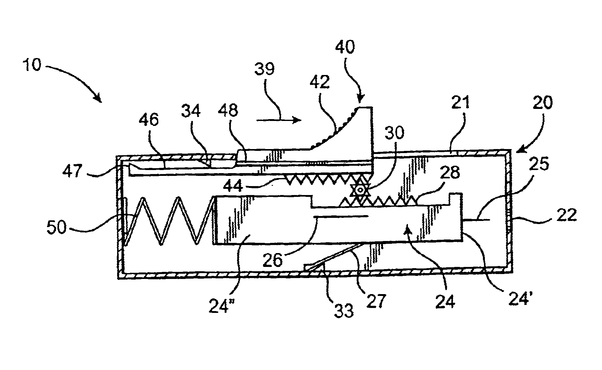
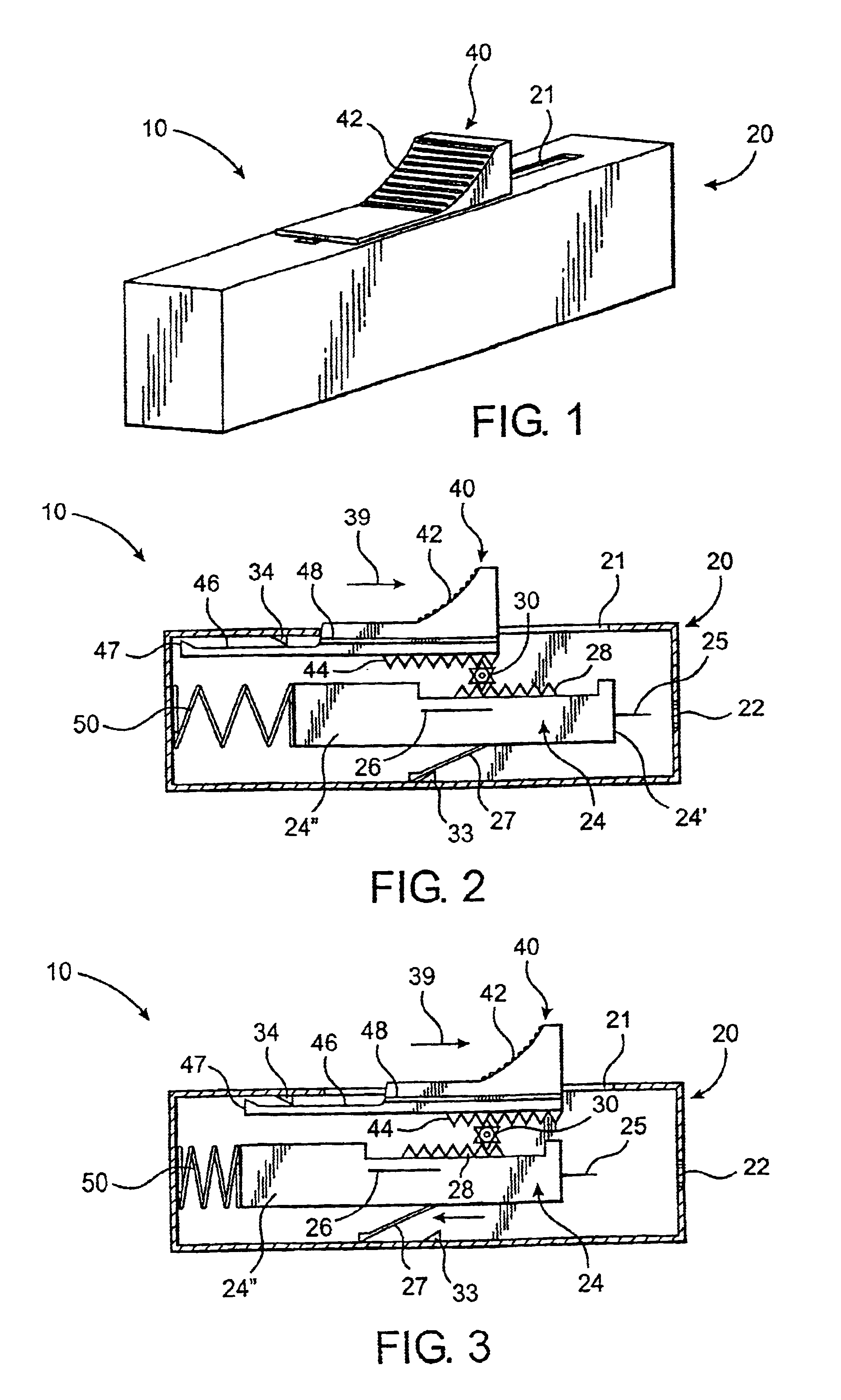
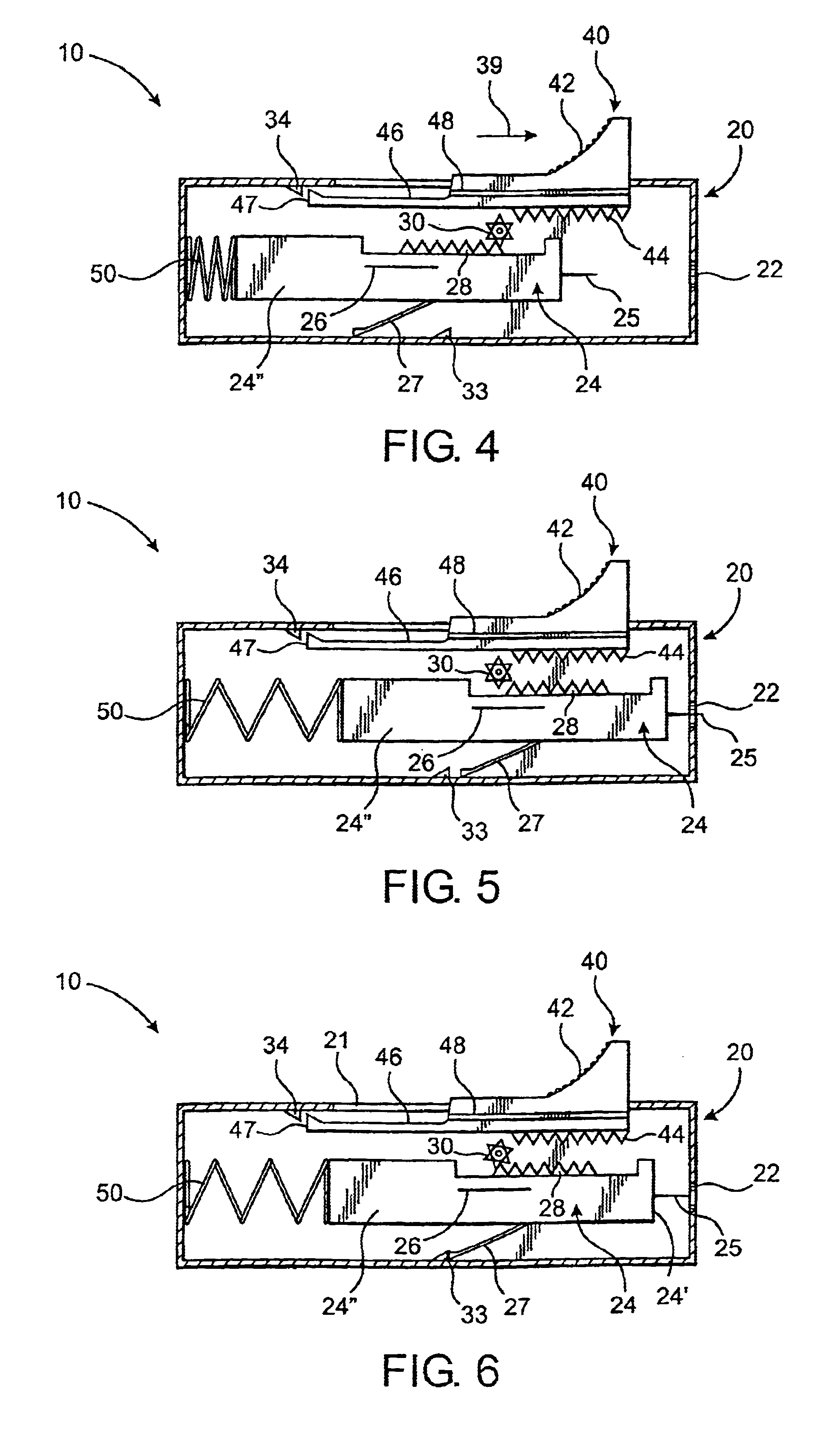
[0027]Looking to the Figures, the present invention is directed to a single use lancet device, generally indicated as 10. In particular, the single use lancet device 10 is structured to be utilized so as to pierce a patient's skin, such as with the piercing tip 25 of a lancet 24 in order to obtain a blood specimen from the patient. Furthermore, the present single use lancet device 10 is preferably configured to be substantially small and compact, and structured so as to permit only a single use thereof. The spread of disease and / or other contaminants from the inadvertent and / or deliberate reuse of such a single use lancet device 10 will thereby be prevented.

[0028]The single use lancet device 10 of the present invention preferably includes a housing 20. The housing 20 is preferably generally rigid and compact so as to be easily and comfortably held and manipulated by the user. In this regard, the housing 20 may be contoured and / or have any configuration that can be effectively and co...


PUM


Abstract

A single use lancet device having a housing, a lancet with a piercing tip movably disposed in the housing and structured to move between a cocked orientation and a piercing orientation, and a driving assembly structured to move the lancet into the piercing orientation. A retention member and an engagement hub are further provided and structured to be cooperatively engaged with one another upon the lancet being disposed in the cocked orientation so as to maintain the lancet in the cocked orientation until released by an actuation assembly. Specifically, the actuation assembly is structured to move between an actuated and an un-actuated orientation, movement into the actuated orientation releasing the retention member and the engagement hub from their cooperative engagement with one another and thereby result in movement of the lancet into the piercing orientation. The device also includes a restrictor assembly structured to substantially prevent the actuation assembly from moving out of the actuated orientation, thereby preventing re-firing of the lancet utilizing the actuation assembly.

Description

CLAIM OF PRIORITY[0001]The present application is a Continuation-In-Part patent application of previously filed, now patent application having Ser. No. 60 / 297,826, filed on Jun. 13, 2001, which is a Continuation-In-Part of U.S. patent application having Ser. No. 09 / 709,738 filed Nov. 10, 2000 now U.S. Pat. No. 6,514,270, also incorporated herein in its entirety by reference.BACKGROUND OF THE INVENTION[0002]1. Field of the Invention[0003]The present invention relates to a single use lancet device structured to be conveniently and effectively utilized for various blood sampling procedure, but which is also substantially safe, preventing re-firing of the device after it has been used, and thereby preventing and / or substantially minimizing inadvertent contamination of a patient and / or other personnel as a result of a used and potentially contaminated lancet. Furthermore, the device is compact and easy to utilize in a cost effective and preferably fully disposable manner.[0004]2. Descrip...

Claims


Application Information

Patent Timeline
Patent Type & Authority Patents(United States)
IPC IPC(8): A61B5/15A61B5/151
CPCA61B5/1411A61B5/15142A61B5/150022A61B5/150259A61B5/150412A61B5/150519A61B5/150916A61B5/15111A61B5/15117A61B5/1513A61B5/15132
Inventor SCHRAGA, STEVEN
Owner SCHRAGA STEVEN
Why Eureka
Try Eureka