Optical sensor and optical process for the characterization of a chemical and/or bio-chemical substance
What is AI technical title?
AI technical title is built by Patsnap AI team. It summarizes the technical point description of the patent document.
a technology of optical sensors and chemical and/or biochemical substances, applied in the direction of optical radiation measurement, speed measurement using gyroscopic effects, material analysis, etc., can solve the problems of front-side in-coupling of light into a waveguide, inapplicability, and inability to permit rapid measuremen
Inactive Publication Date: 2005-10-25
ARTIFICIAL SENSING INSTR ASI
View PDF18 Cites 27 Cited by
Summary
Abstract
Description
Claims
Application Information
AI Technical Summary
This helps you quickly interpret patents by identifying the three key elements:
Problems solved by technology
Method used
Benefits of technology
Benefits of technology
[0030]The referenced sensor signal in the case of the same polarization furthermore has the advantage that disturbances δ, such as, e.g., those caused by temperature fluctuation, light wavelength fluctuation, undesired diffusion of molecules in the waveguides, resp. in the chemo-sensitive layer, unspecific bindings, fluctuations of the concentration of the molecules not to be detected, etc., or combinations of these, can be referenced away, i.e., the referenced sensor signal is independent of δ, because S(signal path)+δ−(S(reference path)+δ)=S(signal path)−S(reference path).
Problems solved by technology
Front-side in-coupling of light into a waveguide (refer to SPIE Vol. 1141, 192-200) is not practical, because a high positioning accuracy is required.
The layout is designed with movable mechanics, which does not permit rapid measurements.
Front side detection is unsuitable for a two-dimensional layout of waveguide grating structure units.
Interferometric measurements are complicated, because the intensities of the two beams have to be matched to one another.
In addition, temperature fluctuations due to the interferometric signal generated by differing polarizations (using a polarizer) are only partially compensated.
This layout, however, is not suitable for an (if necessary simultaneous) (absolute) temperature-compensated measurement on the basis of a direct detection.
Method used
Image
Click on the blue label to locate the original text in one second.
Reading with bidirectional positioning of images and text.
Examples
Embodiment Construction
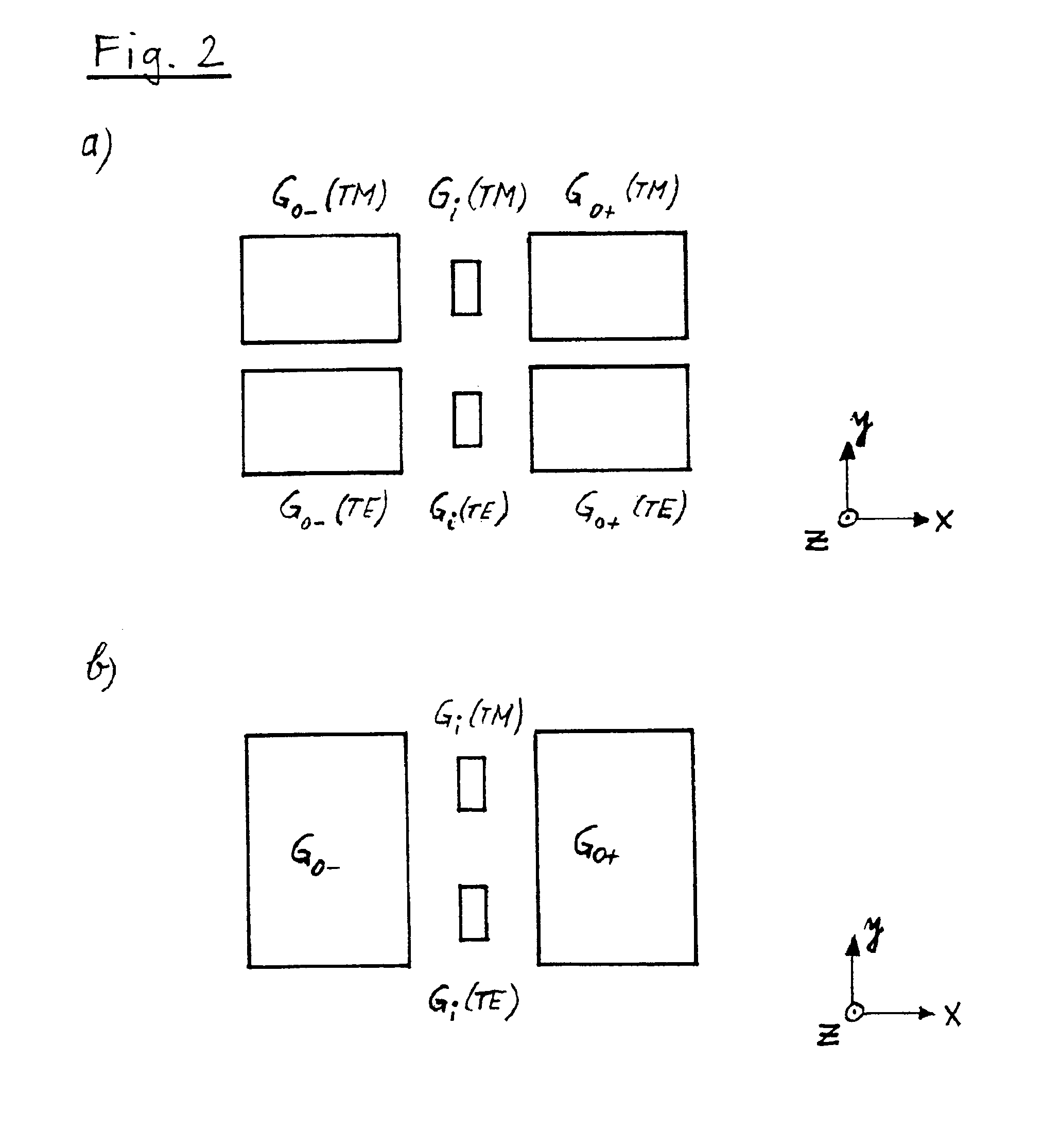
[0038]A further preferred “sensing pad” arrangement also consists of three gratings, whereby the two outer gratings form (possibly more strongly modulated) in-coupling gratings and the middle grating the out-coupling grating.
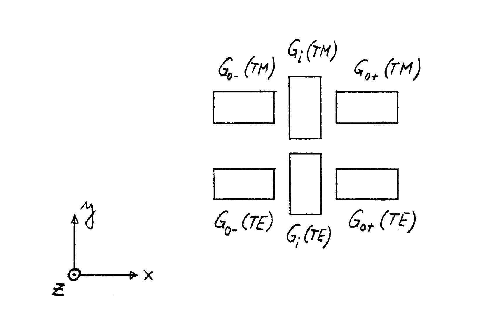
[0039]In case of the detection of (bio-)molecular interactions with the arrangement according to FIG. 1 (or equivalent arrangements), the waveguide structure unit is coated with a (bio-)chemo-sensitive layer, to which then in the experiment a specific binding partner binds, which leads to a change of the out-coupling angles α(TE)=(α(TE+)−α(TE−)) / 2 and α(TM)=(α(TM+)−α(TM−)) / 2 (notation: e.g., α(TE+): out-coupling angle of the TEmode running in +xdirection or to a change of the effective refractive indexes N(TE) and N(TM) and of the integrated optical values derivable from it such as, e.g., of the layer thickness tF of the waveguiding film in the three-layer waveguide model (see further below). Different waveguide grating structure units can be coated with differe...
PUM
Property
Measurement
Unit
in-coupling angles
aaaaa
aaaaa
bio-chemical
aaaaa
aaaaa
chemical
aaaaa
aaaaa
Abstract
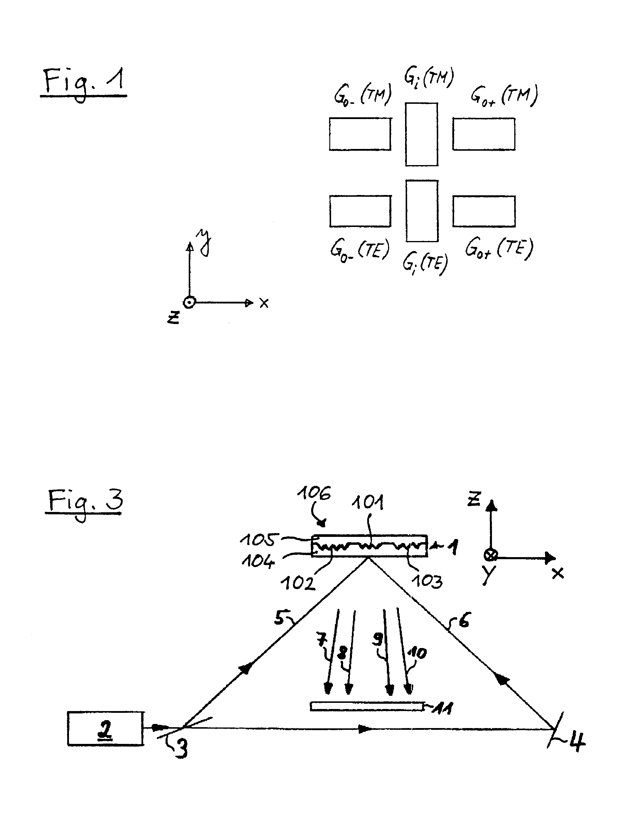
The optical sensor contains an optical waveguide (1) with a substrate (104), waveguiding material (105), a cover medium (106) and a waveguide grating structure (101-103). By means of a light source (2), light can be emitted to the waveguide grating structure (101-103) from the substrate side and / or from the cover medium side. (101-103). With means of detection (11), at least two differing light proportions (7-10) radiated from the waveguide (1) can be detected. For carrying out a measurement, the waveguide can be immovably fixed relative to the light source (2) and the means of detection (11). The waveguide grating structure (101-103) itself consists of one or several waveguide grating structure units (101-103), which if so required can be equipped with (bio-)chemo-sensitive layers. The sensor permits the generation of absolute measuring signals.
Description
CROSS REFERENCE TO RELATED APPLICATIONS[0001]This application is a continuation of U.S. application Ser. No. 10 / 065,152 filed Sep. 22, 2002 now U.S. Pat. No. 6,787,110, published Jan. 9, 2003 as US 2003-0007896 A1, which is a continuation of U.S. application Ser. No. 09 / 508,384 filed Jun. 19, 2000, now U.S. Pat. No. 6,455,004, issued Sep. 24, 2002, which applications are hereby incorporated herein by reference for all purposes.BACKGROUND OF INVENTION[0002]The invention concerns an optical sensor and an optical process for the characterization of a chemical and / or bio-chemical substance.[0003]Waveguide grating structures with and without a chemo-sensitive layer are described in the literature (refer to, e.g., EP 0 226 604 B1, EP 0 482 377 A2, PCT WO 95 / 03538, SPIE Vol. 1141, 192-200, PCT WO 97 / 09594, Advances in Biosensors 2 (1992), 261-289, U.S. Pat. No. 5,479,260, SPIE Vol. 2836, 221-234).[0004]In EP 0 226 604 B1 and EP 0 482 377 A2, it is demonstrated, how the effective refractive...
Claims
Application Information
Patent Timeline
Application Date:The date an application was filed.
Publication Date:The date a patent or application was officially published.
First Publication Date:The earliest publication date of a patent with the same application number.
Issue Date:Publication date of the patent grant document.
PCT Entry Date:The Entry date of PCT National Phase.
Estimated Expiry Date:The statutory expiry date of a patent right according to the Patent Law, and it is the longest term of protection that the patent right can achieve without the termination of the patent right due to other reasons(Term extension factor has been taken into account ).
Invalid Date:Actual expiry date is based on effective date or publication date of legal transaction data of invalid patent.

