Highly efficient focusing waveguide grating coupler using leaky mode

a grating coupler and leaky mode technology, applied in the direction of optical light guides, instruments, optics, etc., can solve the problems of low optical coupling efficiency and large optical focus, and the current lithography technology has a limitation in the fabrication of gratings, so as to reduce the dependency on fabrication processes and high coupling efficiency

Inactive Publication Date: 2005-01-13
ELECTRONICS & TELECOMM RES INST
View PDF7 Cites 32 Cited by
  • Summary
  • Abstract
  • Description
  • Claims
  • Application Information

AI Technical Summary

Benefits of technology

[0029] It is, therefore, an object of the present invention to provide a focusing waveguide grating coupler radiating a single output beam out of the waveguide by using a waveguide having a single leaky-mode, instead of a grating having a short period, the grating which is required in a conventional focusing coupler having a single output beam. In accordance with the present invention, it is possible to fabricate a focusing waveguide grating coupler that has high coupling efficiency with reduced dependency on fabrication processes.

Problems solved by technology

However, to put the optical pickup head to practical use, problems of low optical coupling efficiency and large optical focus should be solved.
Therefore, even if optical losses such as butt-coupling loss and waveguide absorption loss are minimized, it is very hard to obtain the power coupling efficiency to the air layer of over 50%.
Current lithography technology has a limitation in the fabrication of the grating 26 satisfying the above conditions.
Even if it is embodied successfully, it would hardly be reproducible.

Method used


Image

  • Highly efficient focusing waveguide grating coupler using leaky mode
  • Highly efficient focusing waveguide grating coupler using leaky mode
  • Highly efficient focusing waveguide grating coupler using leaky mode

Examples


Embodiment Construction

[0040] Other objects and aspects of the invention will become apparent from the following description of the embodiments with reference to the accompanying drawings, which is set forth hereinafter.

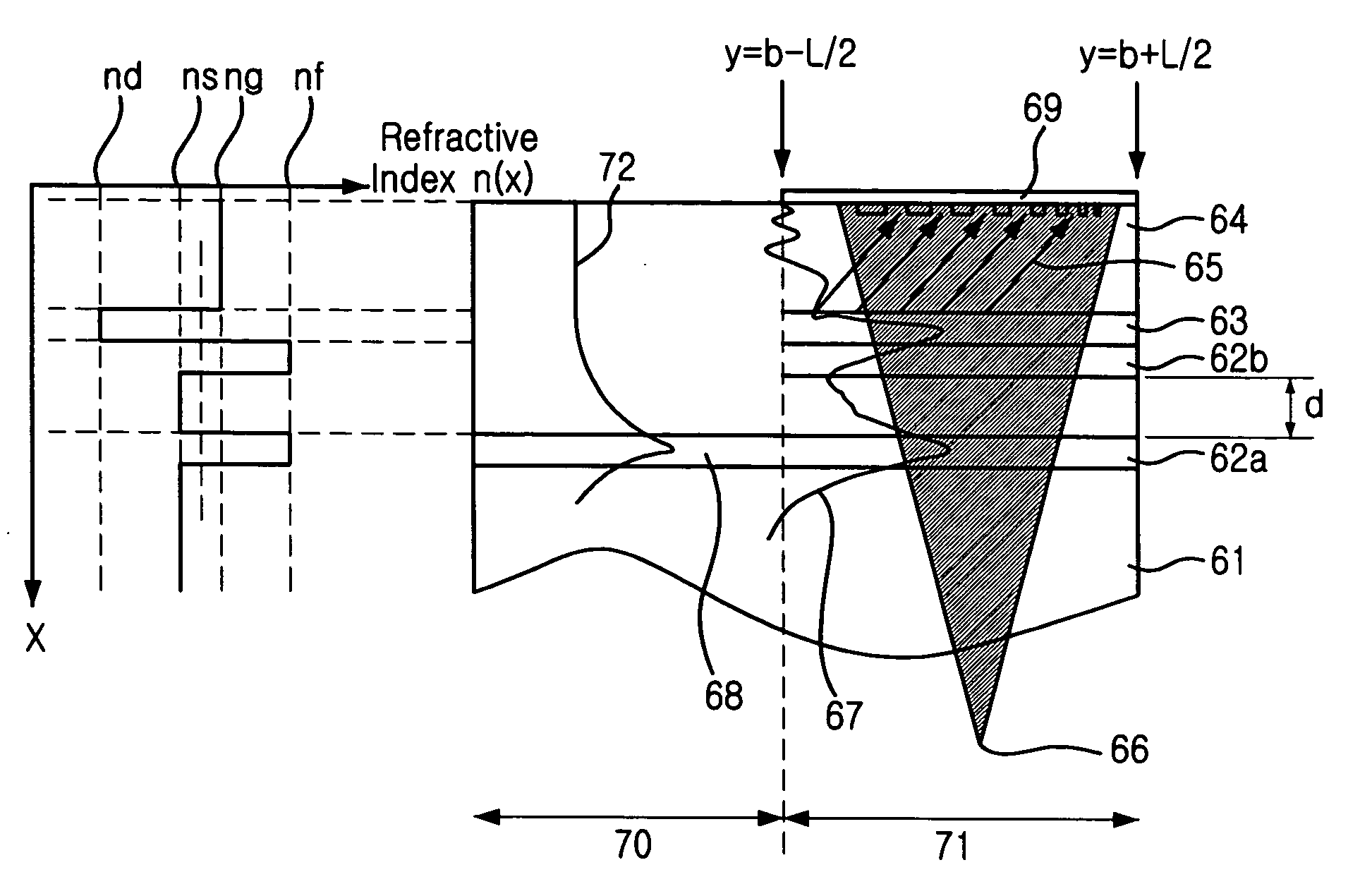
[0041]FIG. 6 is a schematic diagram showing a leaky mode in a leaky mode waveguide in accordance with the present invention. It shows an example of a waveguide where the leaky mode can be formed.

[0042] Referring to FIG. 6, a depressed inner cladding, or inner cladding, 63 is added to a conventional asymmetrical planar waveguide. Specifically, a core layer 62 having a refraction index of nf is placed on a substrate 61 having a refraction index of nc. In the upper part of the core layer 62, the inner cladding layer 63 having a refraction index of nd is formed. In the upper part of the inner cladding layer 63, a top cladding layer 64 having a refraction index of ng is formed.

[0043] The inner cladding layer 63 helps to form a single leaky mode easily by lowering the effective refraction ind...


PUM


Abstract

Provided is a focusing waveguide grating coupler using a leaky mode which can form single output beam while relieving the dependency on manufacturing processes. The focusing waveguide grating coupler of the present research includes: a substrate having a first refraction index n1; a first core layer having a second refraction index n2, the first core layer being formed on the substrate; a second core layer having a third refraction index n3, the second core layer being formed on the first core layer apart from the first core layer with a space d in between; a first cladding layer having a fourth refraction index n4, the first cladding layer being formed on the second core layer; a second cladding layer having a fifth refraction index n5, the second cladding layer being formed on the first cladding layer and inserted between the first core layer and the second core layer; and a Fresnel lens positioned on the second cladding layer, wherein the refractive indexes satisfy conditions of n5>(n2, n3)>n1 and n5>n4; and light inputted through the first and second core layers to the Fresnel lens as radiated leaky beam by a leaky mode formed according to the conditions, and the leaky beam forms an optical focus by performing single directional coupling.

Description

FIELD OF THE INVENTION [0001] The present invention relates to a focusing waveguide grating coupler and, more particularly, to a focusing waveguide grating coupler having enhanced coupling efficiency. DESCRIPTION OF RELATED ART [0002] Focusing waveguide grating lenses become smaller and lighter than conventional lenses such as spheric lenses, aspheric lenses and compound lenses. Since a light source and a detector can be integrated in a waveguide, the miniaturized focusing waveguide grating lenses can be applied to the areas in need of miniaturized lenses, for example, optical disk storages and parts for optical communication systems. [0003] Conventional Fresnel lenses diffract and converge parallel light with a simple Fresnel diffraction grating. The flat Fresnel lenses substitute thick spheric lenses, and they are mostly used for display equipment such as projectors. [0004] However, a grating lens of the present invention is more like a miniaturized focusing light source device, c...

Claims


Application Information

Patent Timeline
Patent Type & Authority Applications(United States)
IPC IPC(8): G02B6/122G02B6/28G02B6/124G02B6/34
CPCG02B6/122G02B6/34G02B6/124G02B6/28
Inventor PARK, YONGWOOSOHN, YEUNGJOONPAEK, MUN-CHEOLSUH, DONG-WOORYU, HOJUNPYO, HYEON-BONG
Owner ELECTRONICS & TELECOMM RES INST
Why Eureka
Try Eureka