Multi-band arrayed waveguide grating

a waveguide and array technology, applied in multiplex communication, instruments, optical elements, etc., can solve the problems of q.times.n awgr modules, reducing yields, and causing the q.times.n awgr modules to be undetectable to manufacture and manage, and the q.times.n awgr modules to be undetectabl

Inactive Publication Date: 2004-01-13
NEOPHOTONICS CORP
View PDF8 Cites 31 Cited by
  • Summary
  • Abstract
  • Description
  • Claims
  • Application Information

AI Technical Summary

Problems solved by technology

A problem encountered in manufacturing such demultiplexers is that variations in manufacturing processes may cause .lambda..sub.0 to depart, from its intended value.
This results in reduced yields because manufactured demultiplexers having values for .lambda..sub.0 falling outside of an acceptable range cannot be used.
Such Q.times.N AWGR modules are, however, undesirably complicated to manufacture and to manage.
Further, the disclosed scheme cannot readily be extended to more than two inputs.

Method used


Image

  • Multi-band arrayed waveguide grating
  • Multi-band arrayed waveguide grating
  • Multi-band arrayed waveguide grating

Examples


first embodiment

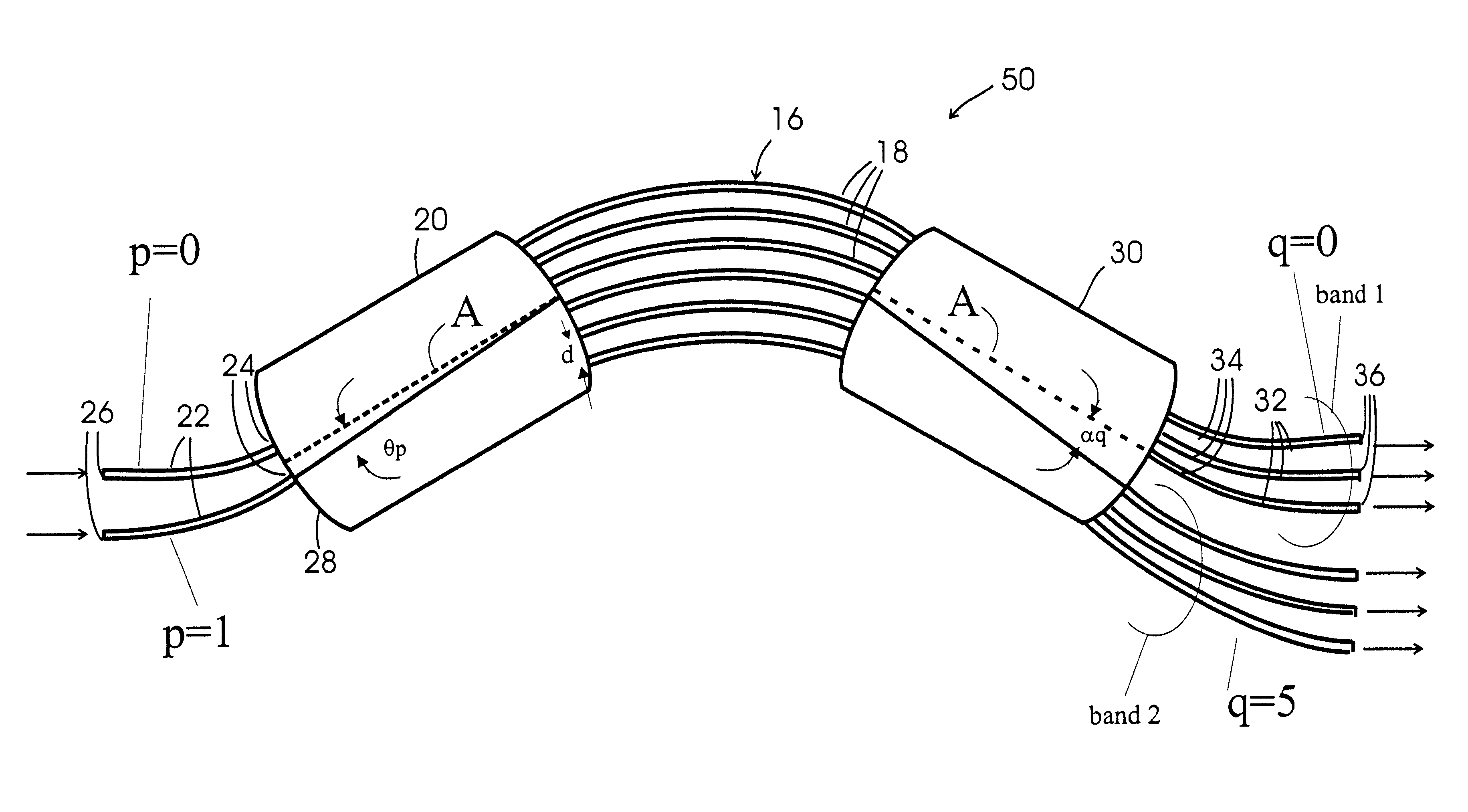
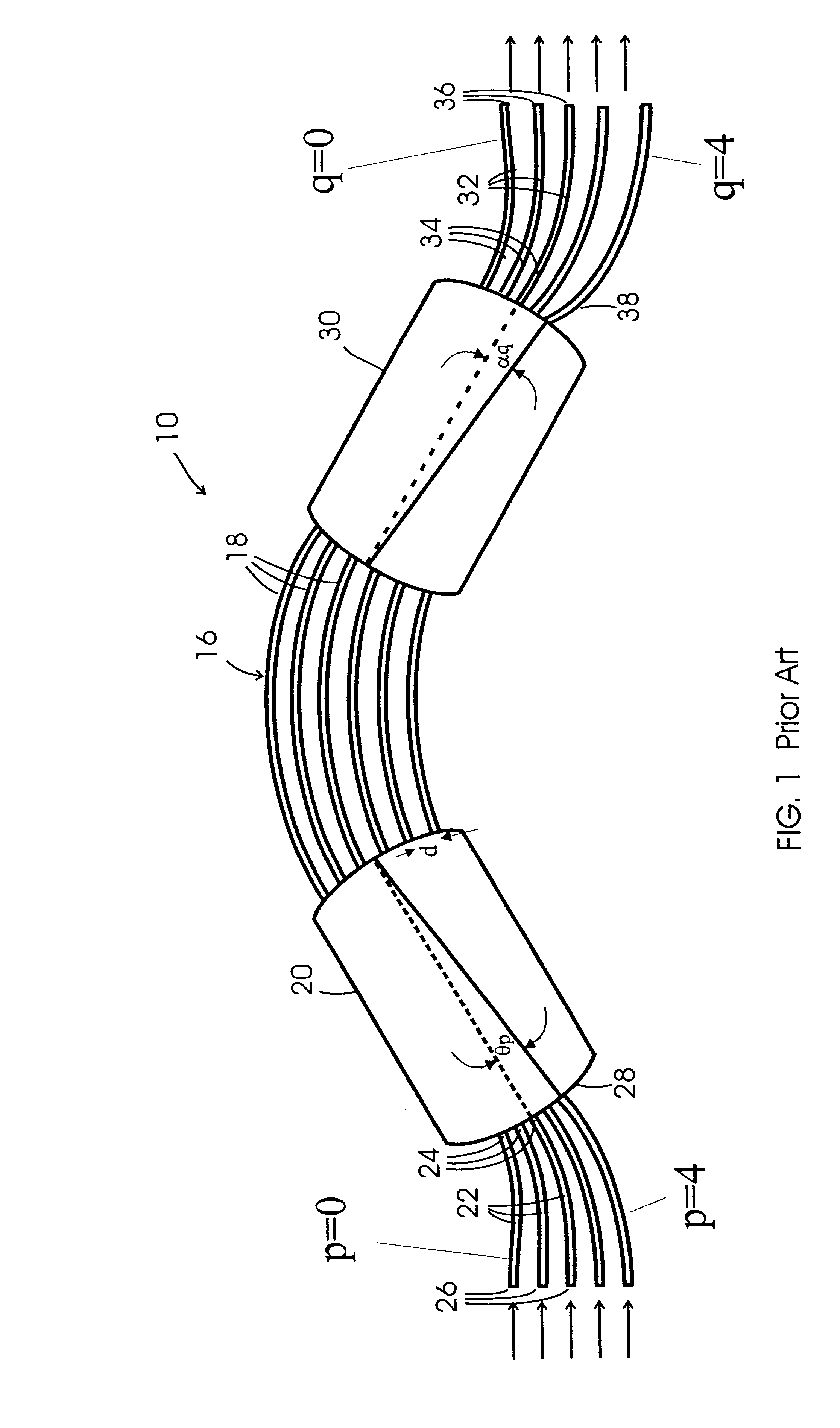
In an AWGR 50 according to the invention, Q.times.N output waveguides 32 are coupled to output slab waveguide 50 at angular locations .alpha..sub.q which satisfy: ##EQU16##

where:

"floor" is the greatest integer function, i.e. its value is the largest integer that is not greater than its argument;

q=0,1,2, . . . (Q N-1);

p=0,1,2, . . . (N-1);

s is a positive integer; and,

e is a number between zero and unity (preferably e is greater than about 0.1).

The plurality of output waveguides is preferably centered at the pole of the output focal curve, which is directly opposite the AWG grating region. That is, preferably:

.alpha..sub.0 +.alpha..sub.QN-1 =0 (18)

N input waveguides are coupled to input slab waveguide 20 at angular locations .theta..sub.p which satisfy: ##EQU17##

Preferably the plurality of input waveguides is centered at the pole of the input focal curve, which is directly opposite the AWG grating region. That is, preferably:

.theta..sub.0 +.theta..sub.N-1 =0 (20)

The AWGR according to ...

second example embodiment

A second embodiment of the invention provides an AWGR 50 having (Q+G-1).times.N output waveguides and G.times.N input waveguides. The output waveguides are coupled to output slab waveguide 30 at angular positions which satisfy: ##EQU24##

The input waveguides are coupled to input slab waveguide 20 at angular positions which satisfy: ##EQU25##

In equations (23) and (24):

q-0,1,2, . . . N(Q+2)-1;

p=floor (q / Q);

g is an integer selected from a predetermined set of integers. In one embodiment g.epsilon.{-1, 0, 1}:

G is the number of members in the set from which g is selected; and,

s.gtoreq.G.

With an AWGR constructed according to equations (23) and (24), the input waveguides are divided into groups with each group of input waveguides associated with a specific value of g. For each value of g there is a target set of output waveguides. The target sets of output waveguides are each divided into N bands with Q passbands within each of the N bands.

FIG. 5A is a block diagram representation of a simp...

third example embodiment

A third embodiment of the invention provides an AWGR 50 having Q.times.N output waveguides 32 coupled to output slab waveguide 30 at angular locations .alpha..sub.q which satisfy: ##EQU26##

N input waveguides are coupled to input slab waveguide 20 at angular positions which satisfy: ##EQU27##

In equations (27) and (28):

c is the speed of light in vacuum; and,

p=floor (q / Q)

As long as p=floor (q / Q) then: ##EQU28##

It can be seen that this embodiment is similar to the first embodiment described above except that the passbands are on a frequency grid rather than a wavelength grid, i.e., the optical frequencies of the passbands are given by:

.nu.=.nu..sub.0 +q.DELTA..nu. (35)

In this embodiment of the invention, when q+2, q+1 and q identify output waveguides within a common band, and n.sub.s is independent of wavelength, the value of R is given approximately by .DELTA..nu. / .nu. which is typically less than 0.001. When one of the output waveguides identified by the indices q+2, q+1 and q is in o...


PUM


Abstract

An arrayed waveguide grating router (AWGR) comprises sets of output waveguides for a number of bands. Angular separation of adjacent output waveguides is relatively small for adjacent output waveguides. within a band and significantly larger for adjacent output waveguides belonging to different bands. In specific embodiments the output waveguides are arranged into at least two bands, each band comprising at least two adjacent waveguides. Each band is used in conjunction with an input waveguide specific to the particular band. AWGRs according to the invention may be made so that the passbands from a plurality of output waveguides fall on a wavelength grid or a frequency grid. Dummy waveguides may be included for ease of fabrication.

Description

This invention is in the field of networks for carrying optical signals. The invention relates to apparatus for multiplexing or demultiplexing a number of optical bands. The invention relates more particularly to such apparatus which incorporates arrayed waveguide gratings.Optical fibers provide a way to transmit large volumes of data from place to place. It is often desirable to wavelength multiplex a number of signals onto a single optical fiber. This can be accomplished by passing each signal into a different input of a multiplexer and connecting an output of the multiplexer to the optical fiber. The signals can be recovered at a destination by demultiplexing.Arrayed waveguide grating routers (AWGRs) are commonly used as multiplexer / demultiplexers in such systems (the same device can typically be used either as a multiplexer, as a demultiplexer, or simultaneously as a multiplexer and a demultiplexer). An arrayed waveguide router uses an arrayed waveguide grating to separate signa...

Claims


Application Information

Patent Timeline
Patent Type & Authority Patents(United States)
IPC IPC(8): G02B6/34
CPCG02B6/12016G02B6/12019
Inventor MCGREER, KENNETHLAM, JANE
Owner NEOPHOTONICS CORP
Why Eureka
Try Eureka