
Multiple drop-volume printhead apparatus and method

a printhead and multi-drop technology, applied in printing and other directions, can solve the problems of small nozzles, puddling or flooding of ink from the far nozzles, and the control of the meniscus oscillation at the far nozzles, so as to reduce nozzle flooding, improve print quality, and reduce nozzle clogging

Active Publication Date: 2005-11-01
SLINGSHOT PRINTING LLC
View PDF13 Cites 34 Cited by
  • Summary
  • Abstract
  • Description
  • Claims
  • Application Information

AI Technical Summary

Benefits of technology

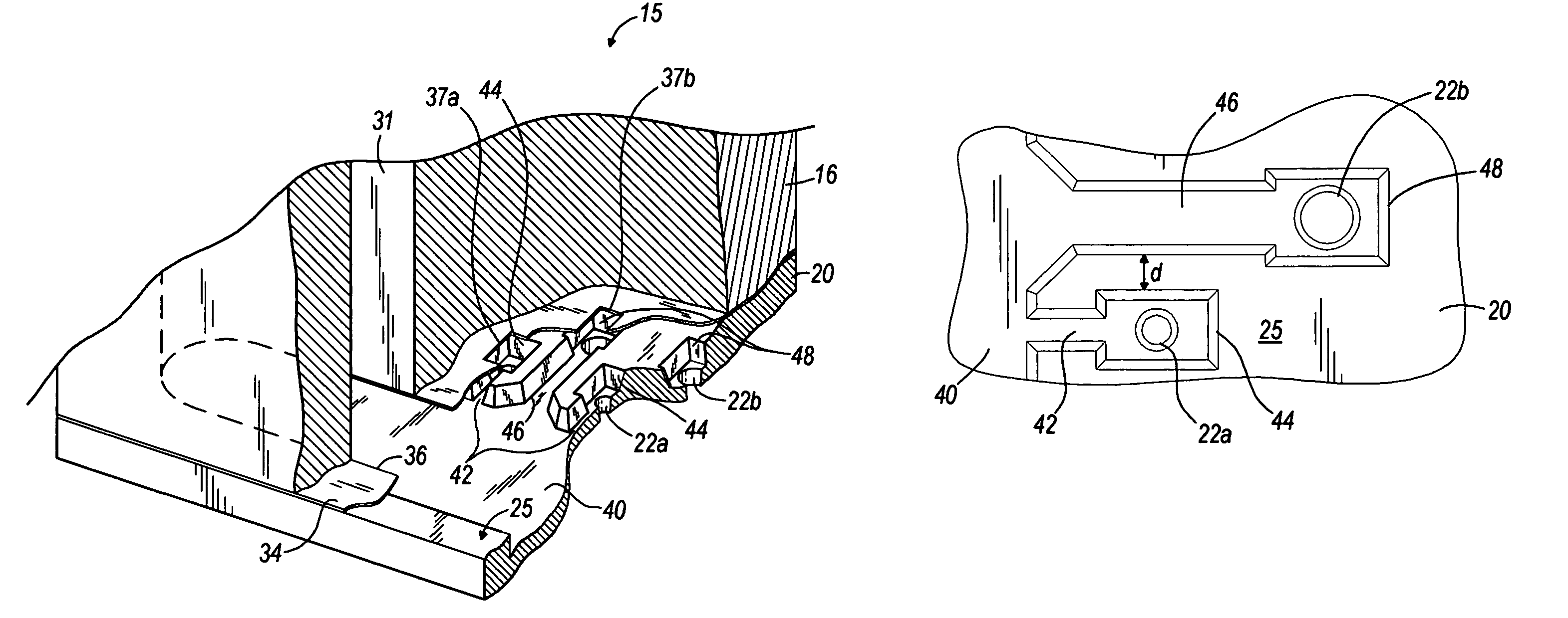
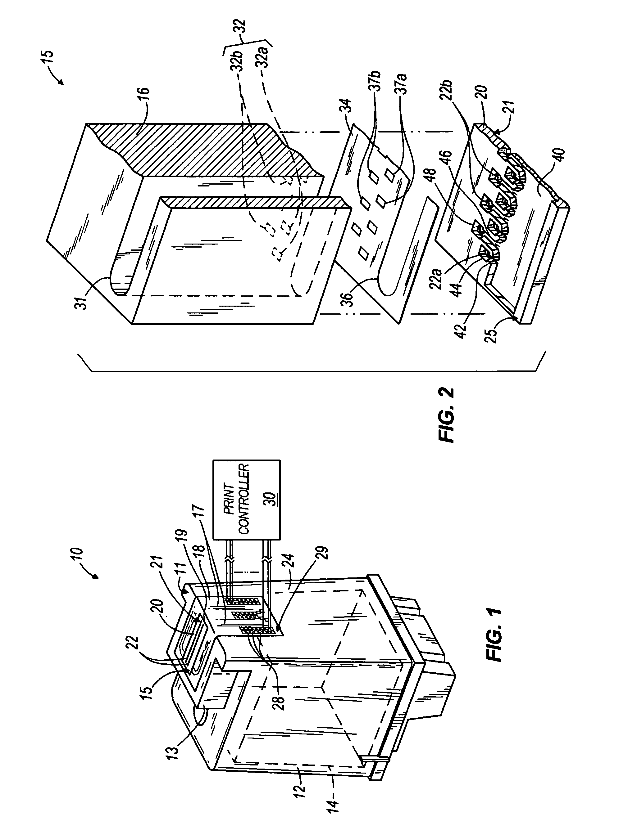
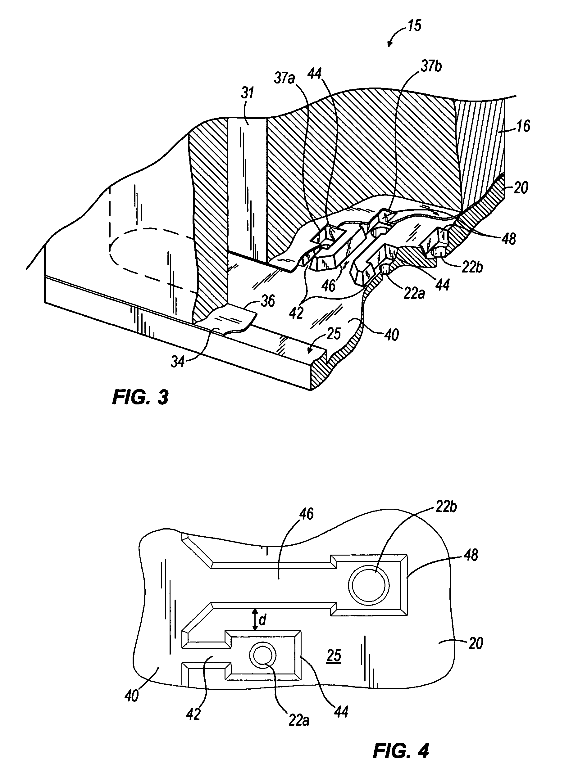
"The present invention provides a printhead with improved refill rates, reduced nozzle flooding, and minimized nozzle plate delamination. The printhead includes a housing, a nozzle plate, and first and second channels in fluid communication with the ink reservoir. The first channels have a first length and terminate in a first nozzle, while the second channels have a second length greater than the first length and terminate in a second nozzle, which is larger than the first nozzle. The method for producing varying ink drop-volumes using the printhead involves positioning the first and second channels at different locations in the nozzle plate."

Problems solved by technology

As a result, the meniscus oscillations at the far nozzles are not as controlled, and overshooting, puddling or flooding of ink from the far nozzles can occur.
However, smaller nozzles (e.g., nozzles capable of producing a 3 nanogram (“ng”) drop of ink) are more susceptible to flooding than larger nozzles (e.g., nozzles capable of producing a 10-ng drop of ink), and positioning smaller nozzles at the less-dampened position can cause flooding from the smaller nozzles and poor print quality.
In addition, smaller nozzles are typically more susceptible to clogging than larger nozzles.
However, this arrangement allows particles larger than the smaller nozzle (i.e., particles having a dimension greater than a cross-sectional dimension of the smaller nozzle) to pass through the channel leading to the smaller nozzle, which can cause clogging of the smaller nozzle.

Method used


Image

  • Multiple drop-volume printhead apparatus and method
  • Multiple drop-volume printhead apparatus and method
  • Multiple drop-volume printhead apparatus and method

Examples


Embodiment Construction

[0016]The present invention generally relates to a printhead having a nozzle portion used to produce multiple print drop-volumes for printing in a variety of modes, including without limitation, draft mode, high-quality mode and a combination thereof.

[0017]As used herein and in the appended claims, the term “ink” can refer to at least one of inks, dyes, stains, pigments, colorants, tints, a combination thereof, and any other material commonly used for inkjet printers.

[0018]As used herein and in the appended claims, the term “printing medium” can refer to at least one of paper (including without limitation stock paper, stationary, tissue paper, homemade paper, and the like), film, tape, photo paper, a combination thereof, and any other medium commonly used in inkjet printers.

[0019]FIG. 1 illustrates an inkjet printhead 10 according to one embodiment of the present invention. The printhead 10 includes a housing 12 that defines a nosepiece 13 and an ink reservoir 14 containing ink or, ...


PUM


Abstract

Flow features in an inkjet printhead. The flow features can include a plurality of first channels, each of the plurality of first channels having a first length and positioned to fluidly communicate with an ink reservoir, and each of the plurality of first channels terminating in a first nozzle. The flow features can further include a plurality of second channels, each of the plurality of second channels having a second length greater than the first length and positioned to fluidly communicate with the ink reservoir, each of the plurality of second channels terminating in a second nozzle, each second nozzle being larger than each first nozzle.

Description

BACKGROUND OF THE INVENTION[0001]Inkjet printheads typically include an ink reservoir in fluid communication with channels that extend to chambers and terminate in nozzles. During printing, drops of ink are ejected from the nozzles onto a printing medium. Smaller drops of ink can be used to produce high-resolution, high-quality prints with little grain. Larger drops of ink can be used to quickly fill high density areas where fine detail is not necessary. One approach to satisfying both of these needs is to produce multiple drop-volumes using the same printhead. In existing systems, nozzles capable of producing varying drop-volumes are arranged at varying distances from an ink reservoir, specifically, “near nozzles” can be positioned at a “near position,” and “far nozzles” can be positioned at a “far position.”SUMMARY OF THE INVENTION[0002]Near nozzles will typically refill at a faster rate than far nozzles at least partly because of the proximity to the ink reservoir. Channels leadi...

Claims


Application Information

Patent Timeline
Patent Type & Authority Patents(United States)
IPC IPC(8): B41J2/14
CPCB41J2/14145B41J2002/14475
Inventor GOIN, RICHARD L.POWERS, JAMES H.
Owner SLINGSHOT PRINTING LLC
Learn More