Reciprocating compressor having an inner core with a scratch resistant intermediate member

a compressor and intermediate member technology, applied in the direction of positive displacement liquid engine, piston pump, magnetic circuit shape/form/construction, etc., can solve the problems of uneven valve opening/closing operation, increased vibration noise of compressor, loose inner stator,

Inactive Publication Date: 2005-11-01
LG ELECTRONICS INC
View PDF16 Cites 15 Cited by
  • Summary
  • Abstract
  • Description
  • Claims
  • Application Information

AI Technical Summary

Benefits of technology

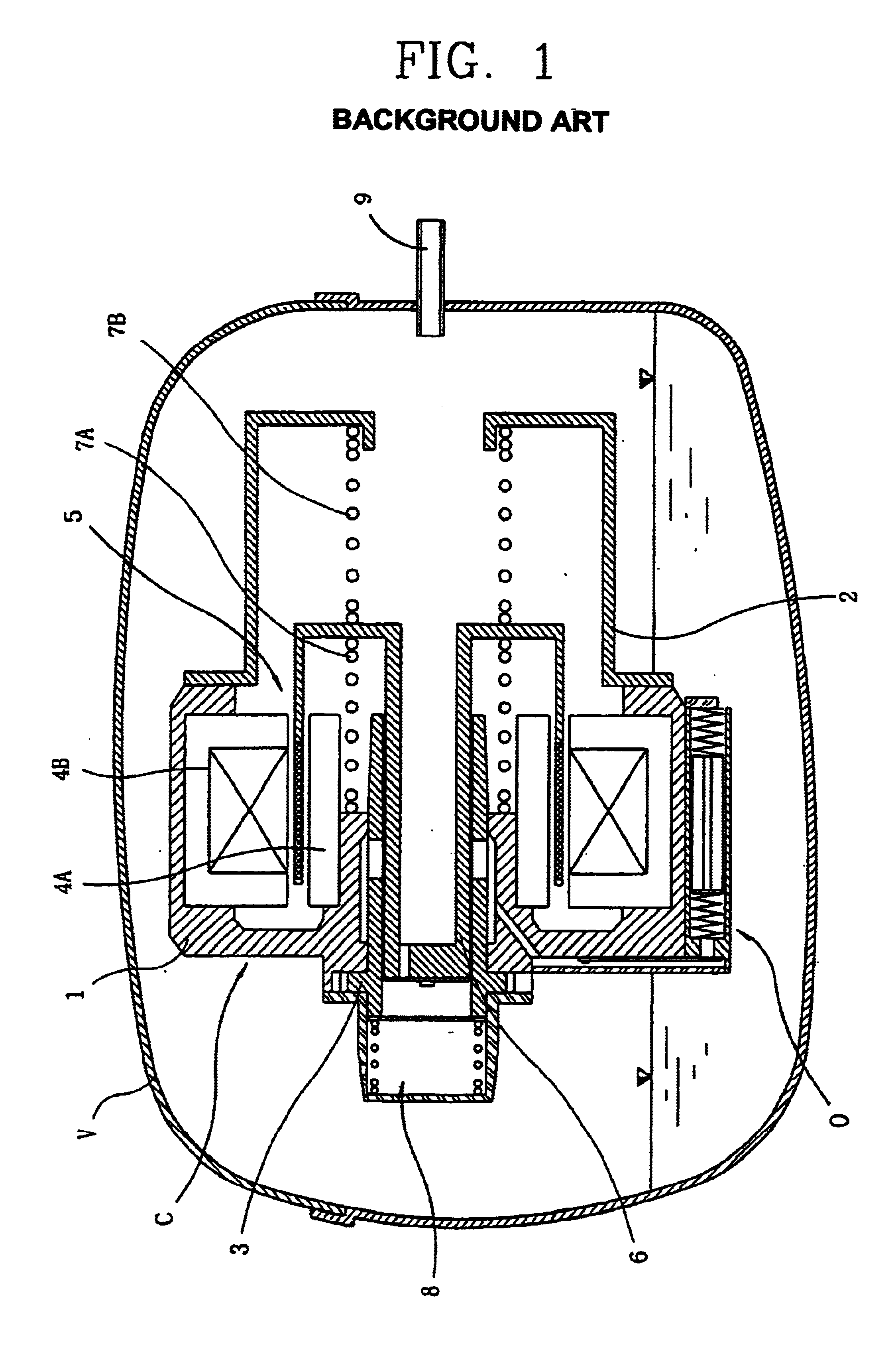
[0014]Therefore, an object of the present invention is to provide a reciprocating compressor which is able to prevent a valve from being damaged by making burr not to generate during press-fitting an inner stator into a frame, and to prevent previously a piston or a cylinder from being damaged caused by inflow of the burr into a sliding portion.
[0015]Also, another object of the present invention is to provide a reciprocating compressor which is able to reduce vibration noise generated by that the coupling status of the frame and the inner stator is loosen during operating the compressor by fixing the frame and the inner stator firmly.

Problems solved by technology

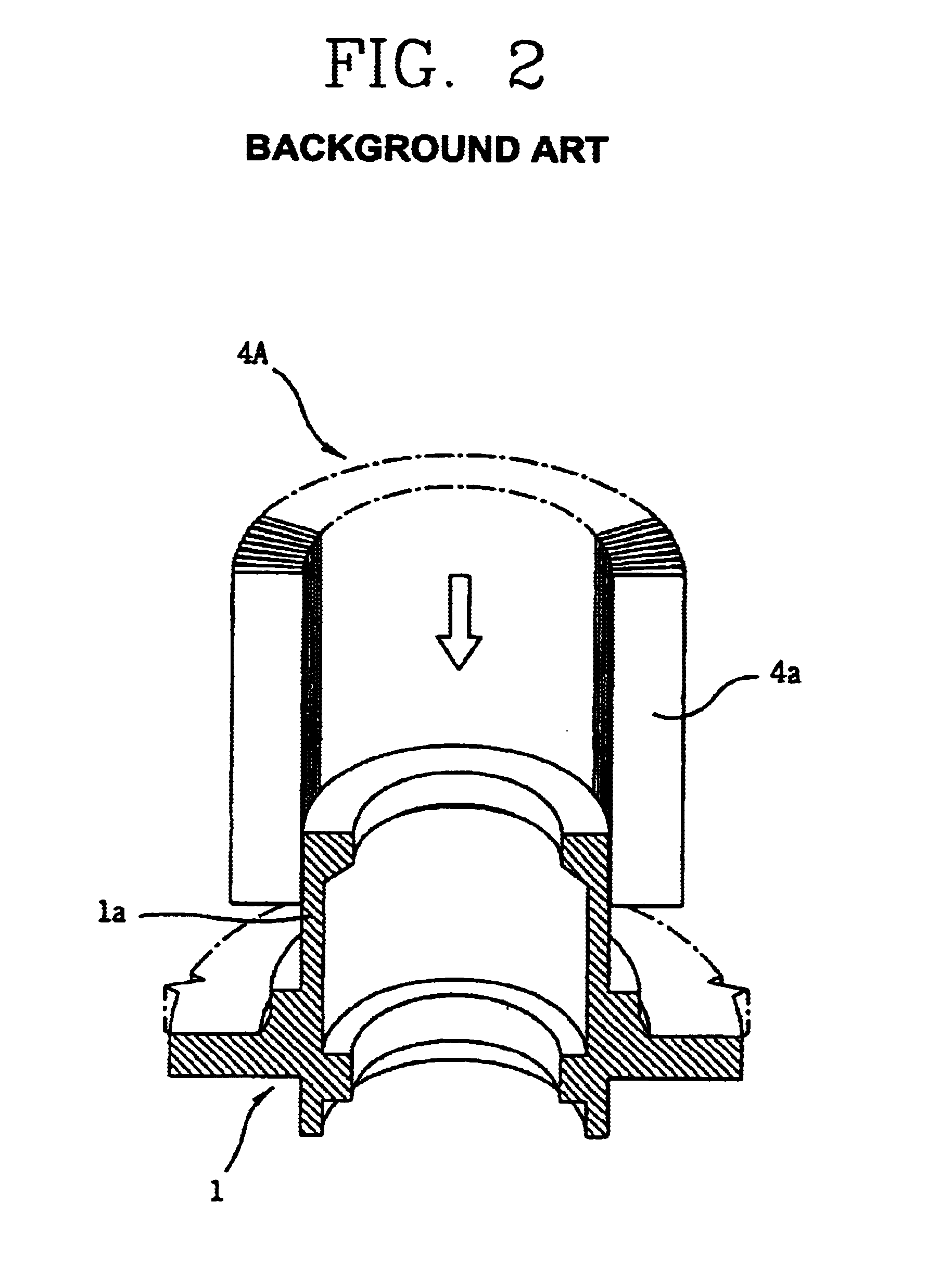
In addition, the burr is induced into the compression chamber with the oil filled in the casing and attached to the valve, and the opening / closing operations of the valve are not made smoothly.
Also, the outer circumferential surface of the boss portion on the frame is worn by the scratches, and accordingly, the inner stator is loosen and the vibration noise of the compressor is also increased.

Method used


Image

  • Reciprocating compressor having an inner core with a scratch resistant intermediate member
  • Reciprocating compressor having an inner core with a scratch resistant intermediate member
  • Reciprocating compressor having an inner core with a scratch resistant intermediate member

Examples


first embodiment

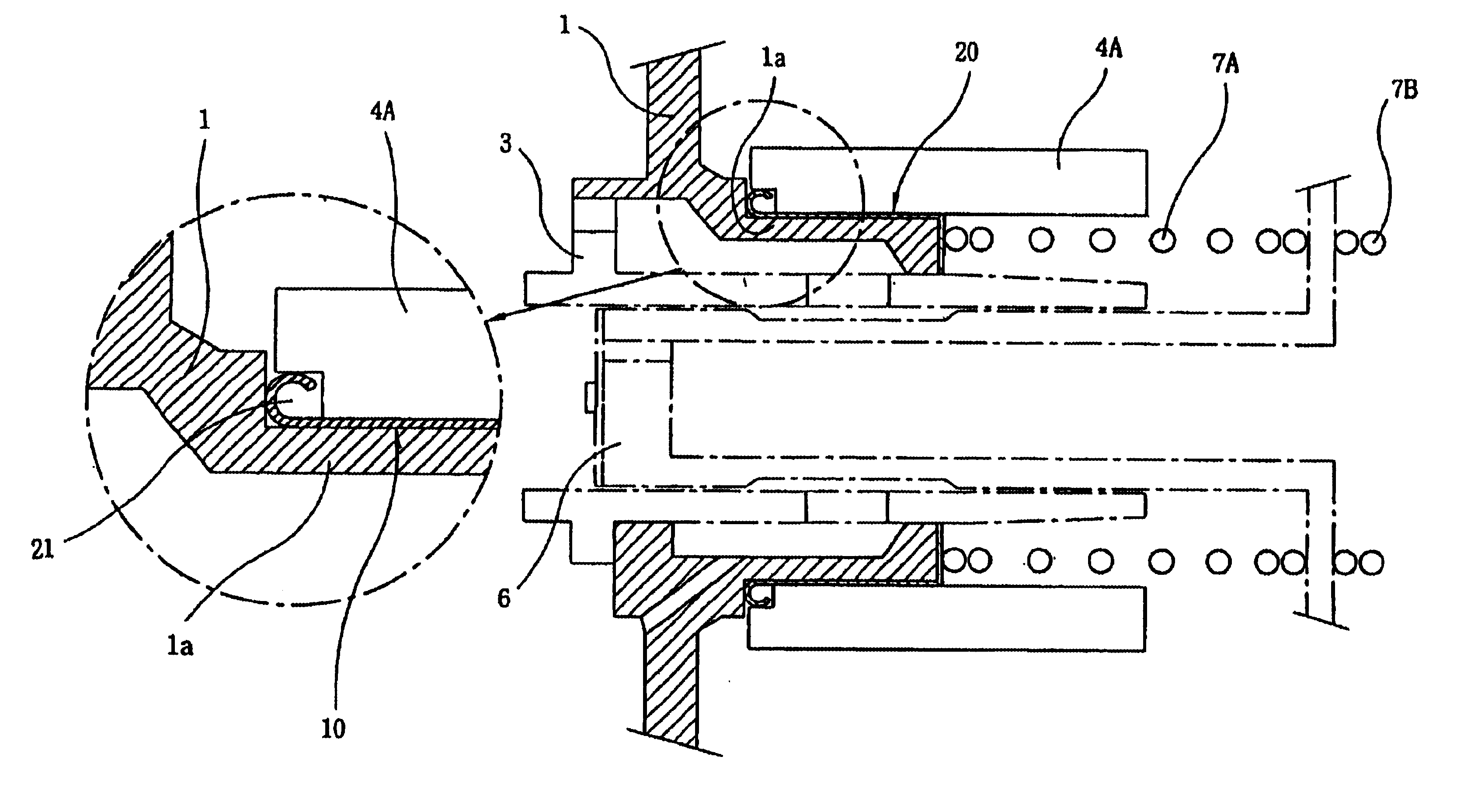
[0019]FIG. 3 is a longitudinal cross-sectional view showing a fixed structure of the inner stator applied by a reciprocating compressor according to the present invention;

[0020]FIG. 4 is a perspective view showing a scratch protection cap of the reciprocating compressor according to the present invention;

[0021]FIG. 5 is a half-perspective view showing a process for mounting the inner stator of the reciprocating compressor according to the present invention;

second embodiment

[0022]FIG. 6 is a longitudinal cross-sectional view showing a fixed structure of the inner stator applied by a reciprocating compressor according to the present invention;

[0023]FIG. 7 is a perspective view showing a burr shielding ring of the reciprocating compressor according to the present invention;

[0024]FIG. 8 is a brief cross-sectional view showing a reciprocating compressor in which a frame and a cylinder are integrated applied by the present invention; and

[0025]FIG. 9 is a brief cross-sectional view showing a reciprocating compressor having a slightly different structure applied by the present invention.


PUM


Abstract

A reciprocating compressor comprises an inside stator formed by piling a plurality of stator cores to have an actinomorphic cylinder shape, which is press-fitted to a frame, and a streak protection member and a burr shielding ring installed between the inner aspect of the inside stator and corresponding outer aspect of the frame. Thereby the burr generating between the frame and the inner stator by a streak is prevented previously, and even if a burr is generated, this burr is locked in a burr escape unit in the burr-shielding ring. Therefore degrading of valve function and an abrasion of a sliding unit in a compressing unit by the burr generating is prevented and the vibration noise of the compressor is reduced by assembling the frame and the inside stator strongly.

Description

[0001]This application is the national phase under 35 U.S.C. §371 of PCT International Application No. PCT / KR01 / 00480 which has an International filing date of Mar. 24, 2001, which designated the United States of America.TECHNICAL FIELD[0002]The present invention relates to a reciprocating compressor, and particularly, to a reciprocating compressor having an inner stator fixing structure in which an inner stator is mounted on a frame and on an inner stator through path pipe.BACKGROUND ART[0003]Generally, a compressor is for changing a mechanical energy into a compressed energy of compressive fluid, and the compressor can be divided into reciprocating type, scroll type, centrifugal type, and vane type compressors.[0004]The reciprocating compressor can be divided into a type in which a driving axis is coupled to an armature of a rotary type driving motor and rotating movements of the driving axis is changed into linear movements of a piston to compress gas, and a type in which a pisto...

Claims


Application Information

Patent Timeline
Patent Type & Authority Patents(United States)
IPC IPC(8): F04B35/00F04B35/04F04B39/00
CPCF04B35/045
Inventor JUNG, WON-HYUNHYEON, SEONG YEOLBAE, GYOO JONGKIM, JANG WHAN
Owner LG ELECTRONICS INC
Why Eureka
Try Eureka