Vibration-proof silent chain

Inactive Publication Date: 2010-12-02
TSUBAKIMOTO CHAIN CO
View PDF14 Cites 9 Cited by
  • Summary
  • Abstract
  • Description
  • Claims
  • Application Information

AI Technical Summary

Benefits of technology

[0007]The invention addresses the above-described problem above by providing a vibration-proof silent chain in which string vibratio

Problems solved by technology

The vibratory force V causes “string vibration” in the free span FS of the chain, which is a main cause of vibration noise, and in

Method used


Image

  • Vibration-proof silent chain
  • Vibration-proof silent chain
  • Vibration-proof silent chain

Examples


first embodiment

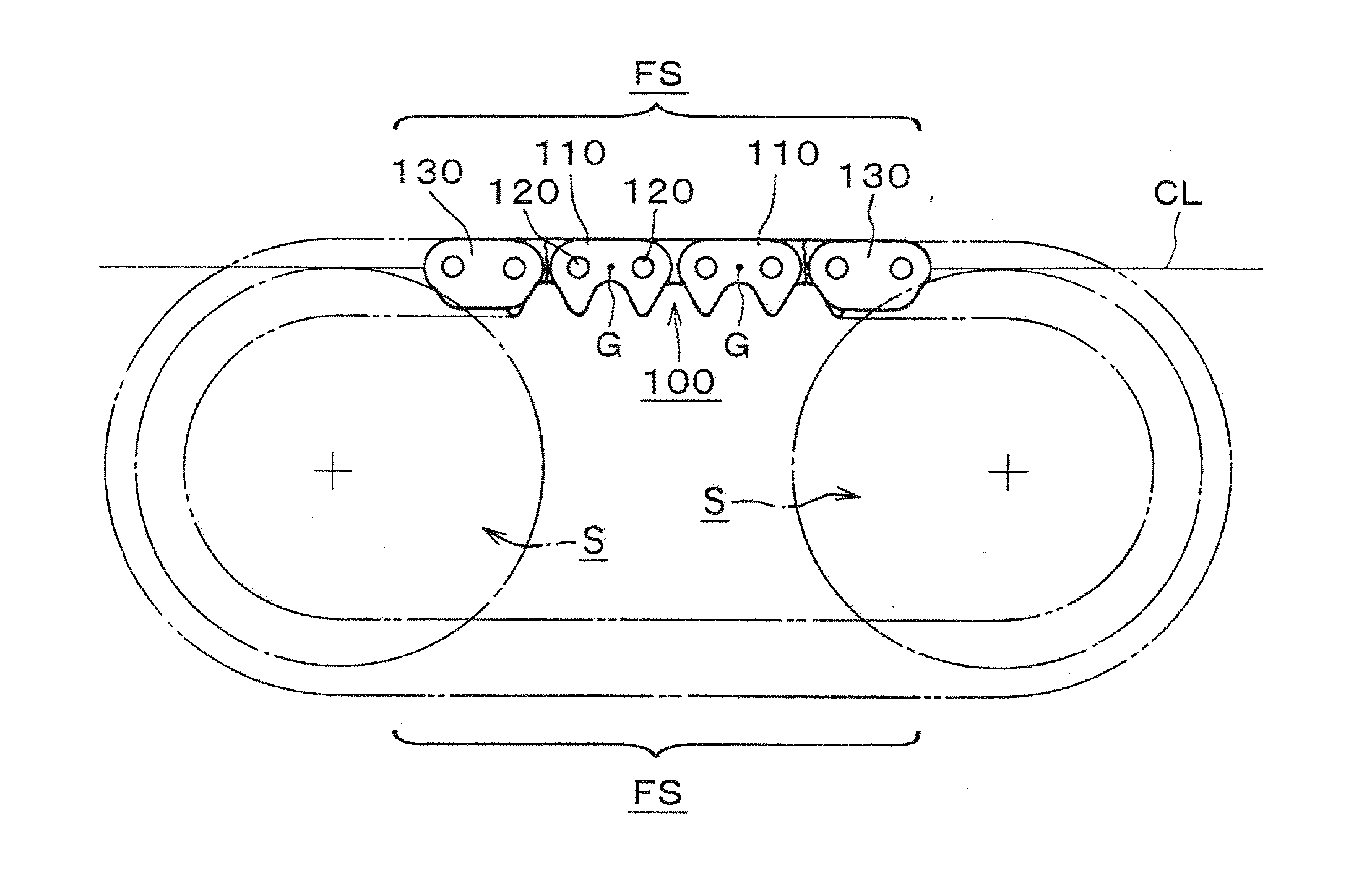
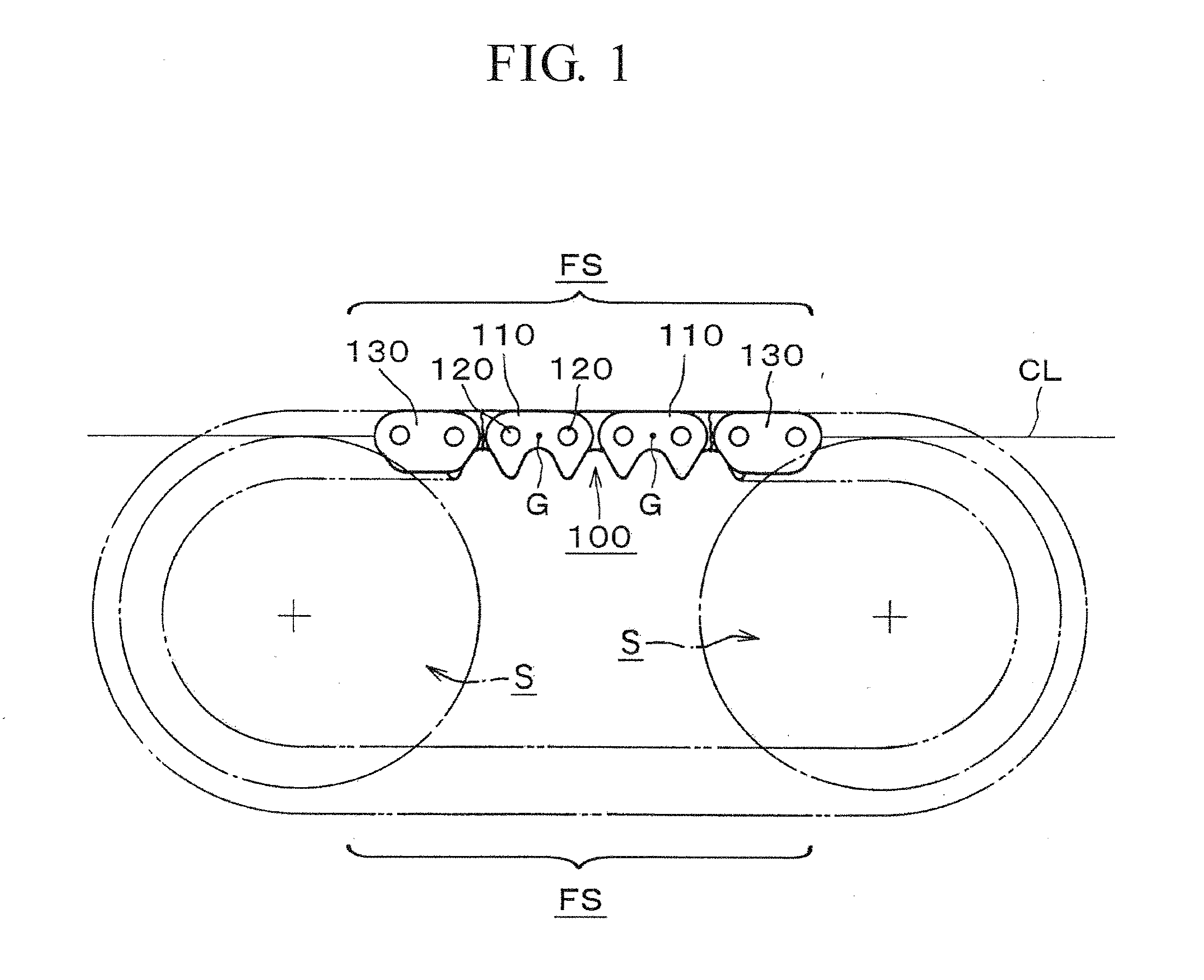
[0034]Accordingly, the vibration-proof silent chain 100 of the invention eliminates string vibration that would otherwise take place in the free spans FS between the sprockets S, reduces vibration noise that accompanies string vibration, and ensures stable chain travel.

[0035]In the embodiment shown in FIG. 4, the center of gravity G of the link plate 210 is also positioned on the chain tension acting line CL in the free span of the chain, which also intersects the centers of the pin holes. In a conventional link plate 510, having its back configured as indicated by the broken line 510 in FIG. 4, the center of gravity would be at position G′. However, because the plate 210 is formed with an enlarged part 211 in the vicinity of the back of the link plate, which improves wear resistance, the center of gravity is moved to position G on the line CL along which chain tension acts.

second embodiment

[0036]Accordingly, while improving wear resistance of the back of the link plate 210, the chain of this second embodiment also eliminates string vibration that would otherwise occur in the free spans of the chain, and avoids vibration noise.

[0037]In the link plate 310 shown in FIG. 5, again the center of gravity G is positioned on the chain tension acting line CL in a free span of the chain, which also intersects the centers of the pin holes. The center of gravity G would be at position G′ except for the presence of weight-reducing holes 311 in the vicinity of the teeth of the link plate, which cause the center of gravity to move from position G′ to position G.

[0038]Accordingly, while reducing the weight of the link plate 310, the holes 311 also cause the center of gravity to become aligned with the tensile force action line, eliminating string vibration that would otherwise occur in the free span of the chain, reduces accompanying noise, and improves stability of chain travel.

fourth embodiment

[0039]In a fourth embodiment shown in FIG. 6, a silent chain 400 includes a large number of link plates 410 linked by connecting pins 420 composed of rocker pins 421 and joint pins 422. Guide plates 430 in FIG. 6 are disposed on the outermost sides of the chain, and the ends of joint pins 422, which are longer than the rocker pins, are press-fit into pin holes in the guide plates. The rocker pins and joint pins fit through the holes in the toothed link plates in such a way that the rocker and joint pins can rock on each other, allowing articulating movement of the adjoining rows of link plates.

[0040]As shown in FIG. 7, the center of gravity G of the link plate 410 is positioned on the chain tension acting line CL in the free span of the chain, which, at least when the free span of the chain is straight and under tension, intersects the lines along which the rocker and joint pins contact each other.

[0041]Even if the traveling line of the chain moves inward and outward due to the chor...


PUM


Abstract

In a silent chain, the toothed link plates are configured so that their centers of gravity are aligned with the line of action of chain tension in a free span of the chain, when the free span is straight and under tension. The positions of the centers of gravity are aligned with the centers of the pin holes in the case of a chain incorporating round connecting pins and are aligned with the points of contact of the rocker pins and joint pins in the case of a chain having rocker joint connecting pins. Positioning of the centers of gravity can be effected by thickening the backs of the link plates or by providing weight-reducing holes in the vicinity of the teeth of the link plates.

Description

CROSS REFERENCE TO RELATED APPLICATIONS[0001]This application claims priority, under Title 35, United States Code, §119 (a)-(d), on the basis of Japanese Patent Application No. 2009-126461, filed on May 26, 2009. The disclosure of Japanese Patent Application No. 2009-126461 is herein incorporated by reference in its entirety.FIELD OF THE INVENTION[0002]This invention relates to a silent chain for the use as a timing chain in an automobile engine and as a power transmission chain in industrial machinery, for example.BACKGROUND OF THE INVENTION[0003]FIG. 8 of the drawings shows a known silent chain 500 for use in an engine or other mechanism requiring power transmission. The silent chain is composed of rows of link plates, each row comprising a plurality of link plates 510 arranged in side-by-side, spaced relationship in the direction of the width of the chain. The plates of the rows are interleaved and linked by connecting pins 520 inserted through pin holes in the link plates. The l...

Claims


Application Information

Patent Timeline
IPC IPC(8): F16G13/04
CPCF16G13/04
Inventor KABAI, TSUYOSHI
Owner TSUBAKIMOTO CHAIN CO
Why Eureka
Try Eureka