Bearing device for supporting pinion shaft

a technology of bearing device and pinion shaft, which is applied in the direction of bearing unit rigid support, gearing details, gearing, etc., can solve the problems of lowering the efficiency and affecting the operation of the differential devi

Inactive Publication Date: 2007-10-30
JTEKT CORP
View PDF5 Cites 11 Cited by
  • Summary
  • Abstract
  • Description
  • Claims
  • Application Information

AI Technical Summary

Problems solved by technology

This leads to a larger rotational torque, which results in lowered efficiency of the differential device.
Other drawbacks are: torque, on account of using oil for lubrication, increases due to a resistance caused by the agitated oil, it becomes necessary to provide the oil introducing path 11 and the oil reflux path in the differential case 1 resulting in the differential device of a larger size, and the bearing device, under the influence from foreign matter in the oil, undergoes a shortened life and requires maintenance.

Method used


Image

  • Bearing device for supporting pinion shaft
  • Bearing device for supporting pinion shaft
  • Bearing device for supporting pinion shaft

Examples


Embodiment Construction

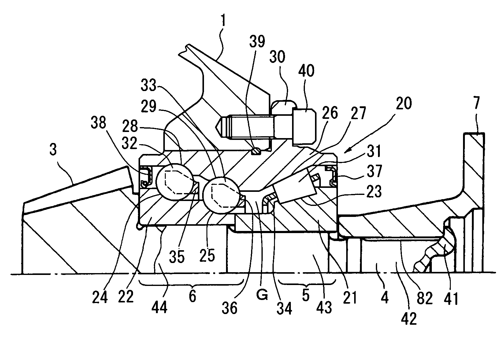
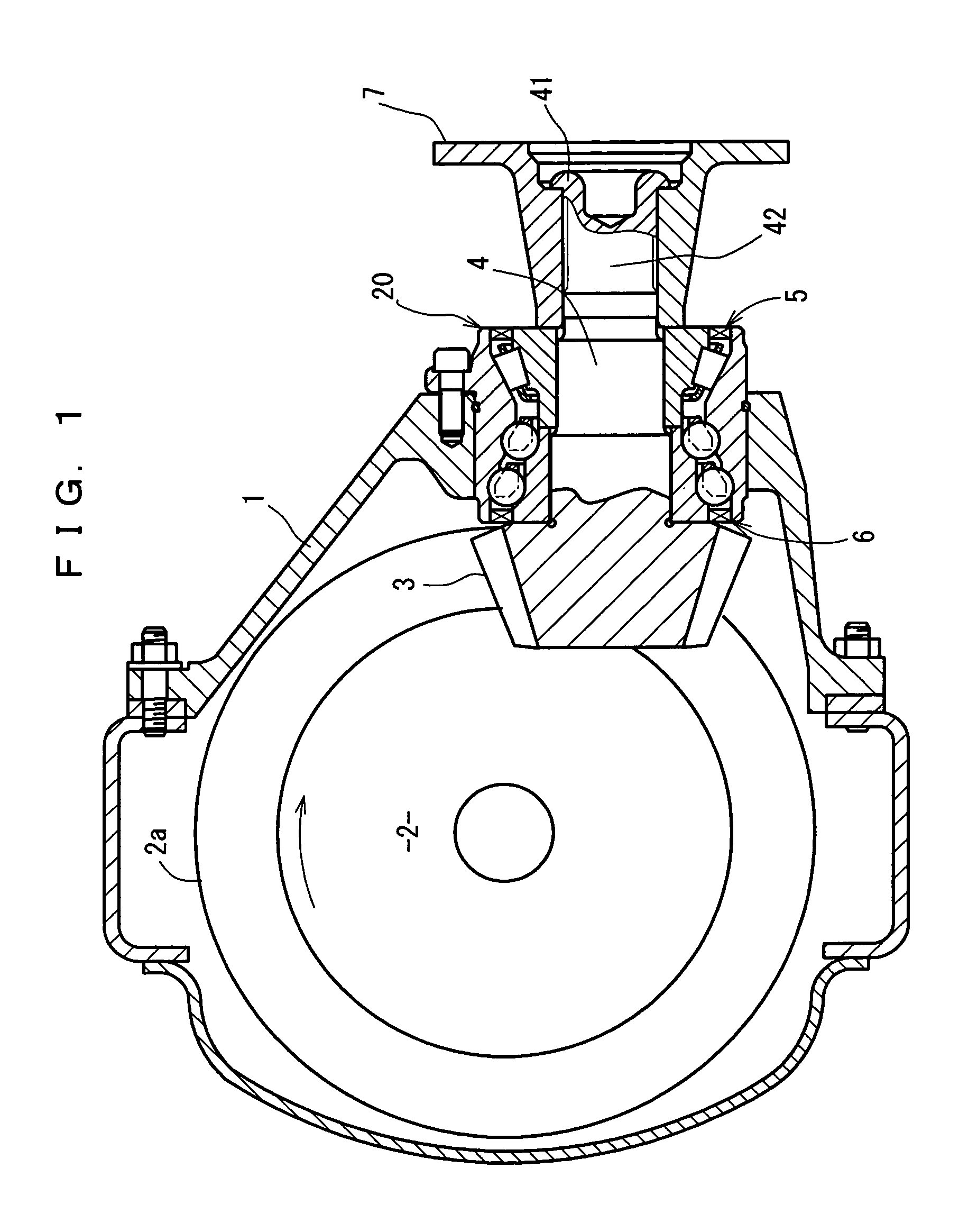
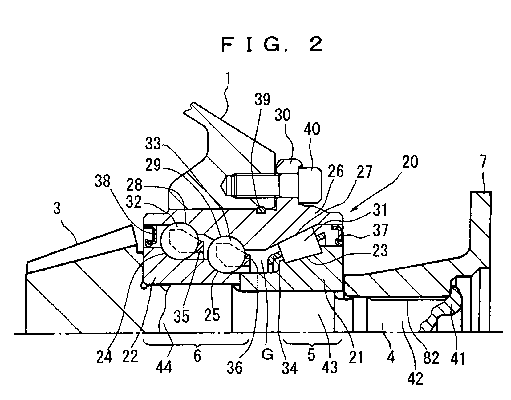
[0024]Referring to FIGS. 1 through 3, a bearing device for supporting a pinion shaft according to a preferred embodiment of the present invention is hereinafter described. FIG. 1 shows a sectional view of a differential device having a bearing device for supporting a pinion shaft adopted therein. FIG. 2 shows a partial sectional view of the bearing device for supporting a pinion shaft. FIGS. 3A and 3B show an enlarged sectional view of sealed portions in the bearing device for supporting a pinion shaft. 1 is a differential case, 2 is a differential speed change mechanism for differentially gearing right and left wheels, 3 is a pinion gear engaged with a ring gear 2a of the differential speed change mechanism 2, 4 is a pinion shaft integral with the pinion gear 3, and 20 is a bearing unit for supporting the pinion shaft 4 so as to freely rotate with respect to the differential case 1.

[0025]The bearing unit 20 comprises a first tilt-contact rolling bearing 5 formed from a companion-fl...


PUM


Abstract

The present invention relates to a bearing device for supporting a pinion shaft so as to freely rotate with respect to a case. The bearing device comprises a first tilt-contact rolling bearing provided on the connecting-flange-side outer peripheral surface of the pinion shaft and a second tilt-contact rolling bearing formed from an angular ball bearing provided on the pinion-gear-side outer peripheral surface of the pinion shaft, wherein lines of action of the first and second tilt-contact rolling bearings intersect with one another on an outer diameter side, the connecting-flange-side end portion of the first tilt-contact rolling bearing and the pinion-gear-side end portion of the second tilt-contact rolling bearing are respectively sealed with seal members, a sealed space between the seal members is infilled with grease, and the connecting flange is fastened in the pinion-gear direction to thereby preload the first and second tilt-contact rolling bearings.

Description

TECHNICAL FIELD[0001]The present invention relates to a bearing device for supporting a pinion shaft so as to freely rotate, more particularly to a bearing device for supporting a pinion shaft comprised of a pair of tilt-contact rolling bearings installed in axial proximity and lubricated with grease.BACKGROUND ART[0002]The structure of a conventional differential device is shown in FIG. 12.[0003]In FIG. 12 is shown a differential speed change mechanism 2 for differentially gearing right and left wheels, a pinion gear 3, a pinion shaft 4, and tapered roller bearings 50 and 60 for supporting the pinion shaft 4 so as to freely rotate, which are housed in a differential case 1. The pinion gear 3 is engaged with a ring gear 2a of the differential speed change mechanism 2 and is integral with the pinion shaft 4 at the inner end portion thereof. The pinion shaft 4 is supported, so as to freely rotate, on the inner side of the differential case 1 by the single row tapered roller bearings 5...

Claims


Application Information

Patent Timeline
Patent Type & Authority Patents(United States)
IPC IPC(8): F16C19/49F16C19/16F16C19/18F16C19/36F16C19/54F16C33/66F16C33/78F16C35/06F16H1/14F16H48/42F16H57/021F16H57/037
CPCF16C19/163F16C19/364F16C19/492F16C19/54F16C33/6611F16C33/6614F16C33/6622F16C33/6633F16C33/7869F16H57/021F16H57/037F16C19/182F16C2361/61F16C2240/80F16H1/145F16H2048/423F16C35/067F16C19/548F16C19/542
Inventor DODORO, HIROFUMISUZUKI, AKIYUKIKOUDA, KANICHIKAWAMURA, MOTOSHIYOKOTA, KUNIHIKOFUKUDA, TOSHIROU
Owner JTEKT CORP
Why Eureka
Try Eureka