Utility machinery and associated control arrangements

a technology of control arrangement and utility machinery, which is applied in the direction of threshers, gearing, hoisting equipment, etc., can solve the problems of spring sticking out, high maintenance requirements, and weight, cost and complexity,

Active Publication Date: 2004-03-04
BLUE LEAF I P INC
View PDF14 Cites 13 Cited by
  • Summary
  • Abstract
  • Description
  • Claims
  • Application Information

AI Technical Summary

Benefits of technology

[0034] c) a torque dependent pressure device comprising at least one wedge member disposed on one of said sleeve and said hub and an associated wedge track disposed on the other of said sleeve and said hub, said wedge member being arranged in use in the event of belt slippage to rotate said sheave members relative to each other and to move along said wedge track in such a manner as to force said sheaves towards each other and thereby to increase grip on said belt,
[0036] One advantage of this arrangement is to provide protection for said wedge and track members from environmental hazards.

Problems solved by technology

While a chain drive can offer high efficiency in power transmission, this form of drive tends to have quite a high maintenance requirement, e.g. in terms of chain lubrication.
A more significant disadvantage is felt when a change in transmission ratio is required, under which circumstances it may prove necessary to fit one or more gearboxes into the drive line or to provide multiple sprocket sets and thereby add weight, cost and complexity.
One disadvantage of such an arrangement is that the casing holding the spring sticks out to one side.
This will incur a width penalty equal to the depth of the spring casing.
As the spring is pushing against the moveable sheave, this arrangement would therefore mean that the moveable sheave is also outboard and its associated control linkages may be both vulnerable to damage and may still further increase width or interfere with other mechanisms.
Such an arrangement, however, is difficult to meet because the space available between the variator and the frame may not be wide enough to accommodate the spring housing or associated control linkages.
If the load is too low, slippage and hence loss of power will occur.
However, the load may not be increased infinitely, because the lifetime of a belt decreases dramatically if the axial load is too high.
It is a disadvantage of the proposal in GB-1555162 that this cam mechanism is external to the pulley, where it is exposed to environmental hazards such as dust or grease.
This mechanism also operates by constantly pushing the moveable sheave against the fixed sheave, which may limit the life of some components such as thrust bearings.
Such backlash causes premature wear to the cams and their supports.
In addition, it may be noted that the sensitivity of the control mechanism at high belt pitch is the same as it is at low belt speeds and this may limit the changes in pitch and associated speed changes which can be made per increment in sheave separation.
This can lead to problems achieving overall width limits for road transport, e.g. three meters, whilst still providing a sufficiently wide frame for materials handling.
In this arrangement, however, fixed ratio driven wheels are positioned behind an engine driven input wheel and this might lead to complicated and lengthy ratio changes.

Method used


Image

  • Utility machinery and associated control arrangements
  • Utility machinery and associated control arrangements
  • Utility machinery and associated control arrangements

Examples


Embodiment Construction

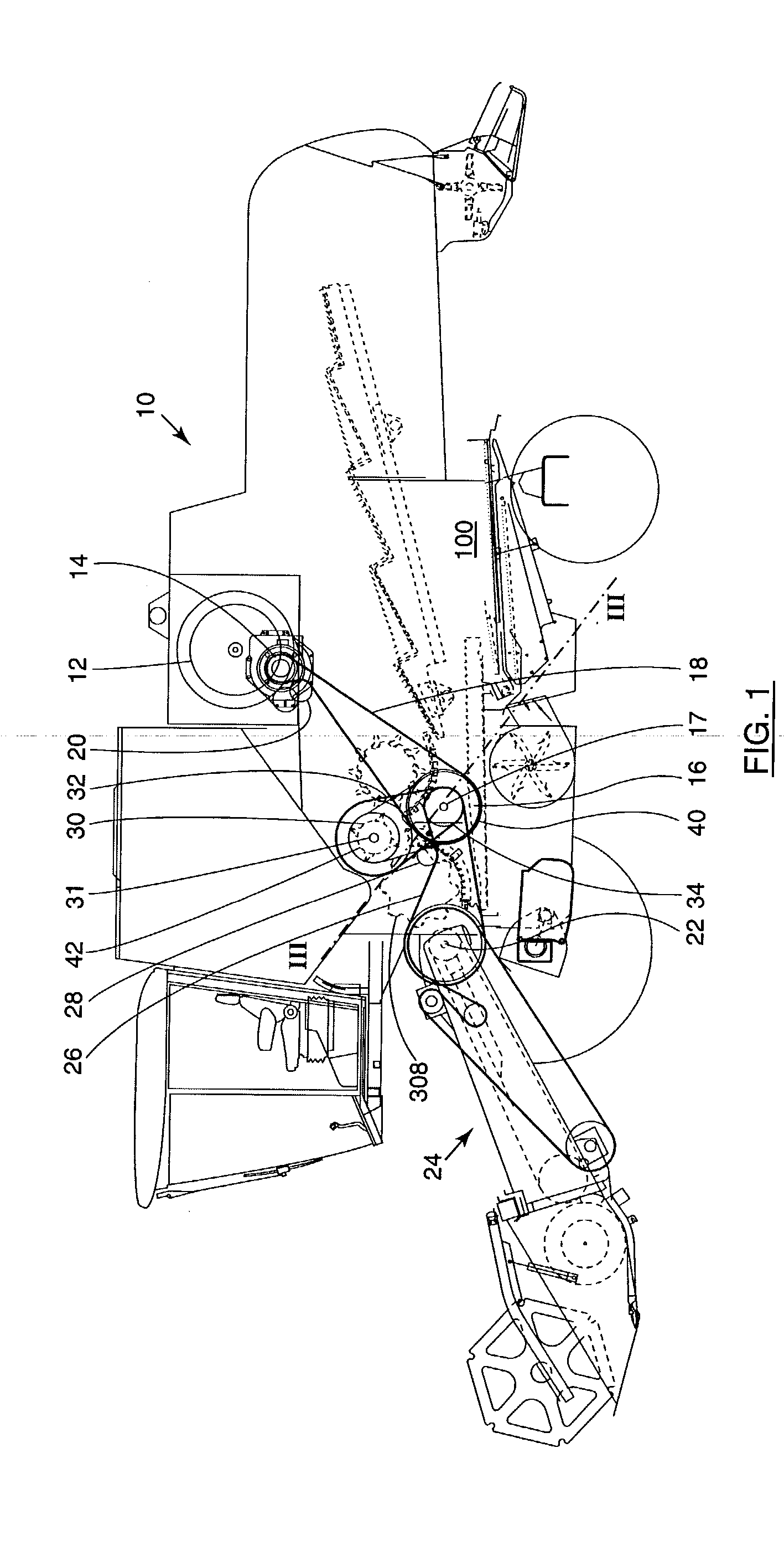
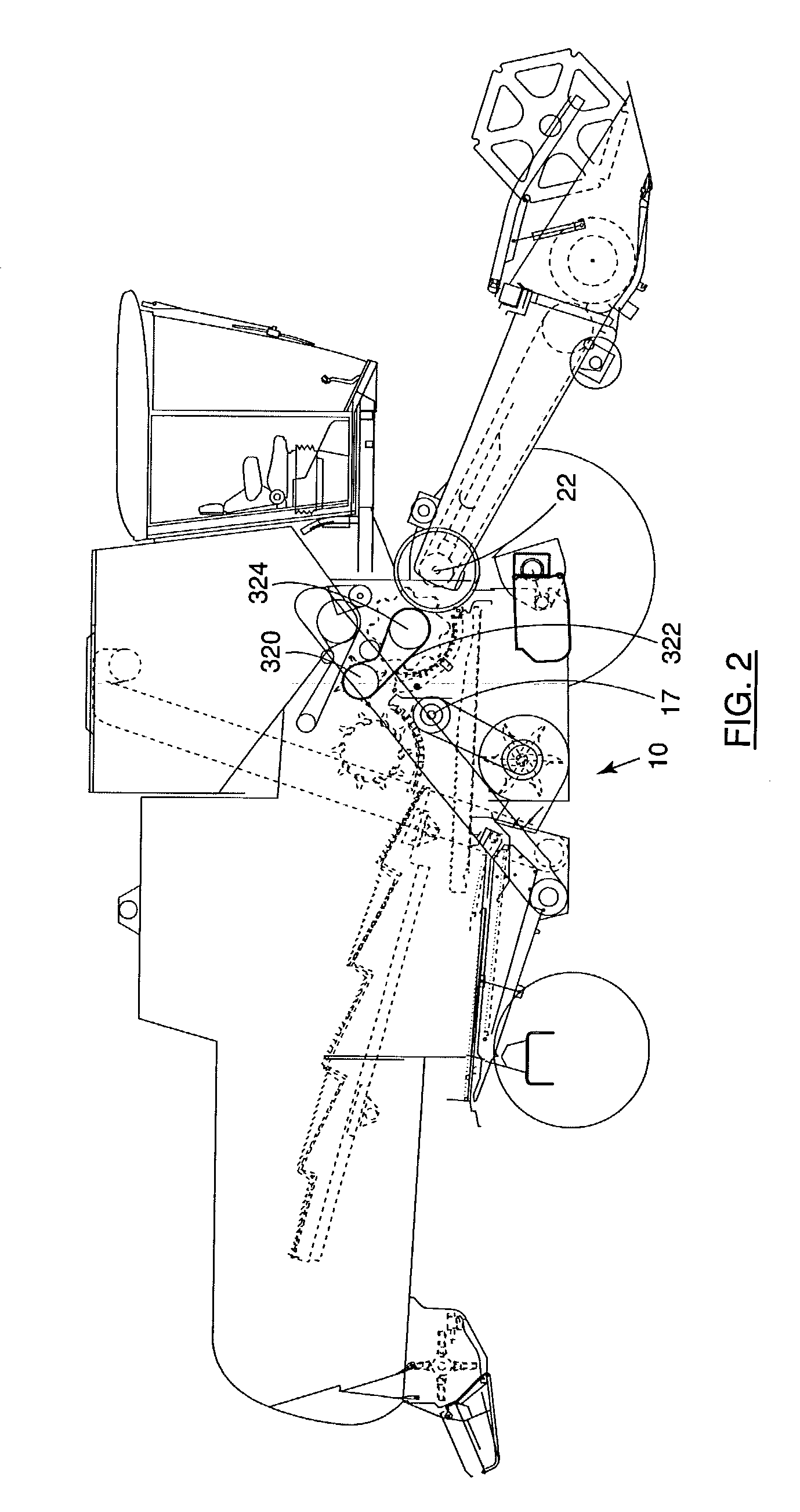
[0070] The drawings are schematic and the terms "front", "rear", "forward", "rearward", "right and "left" where used are determined with respect to the normal direction of movement of the machine in use. For convenience, the specific but non-limiting examples discussed herein will concentrate on agricultural machinery and in particular self-propelled combine harvesters, although it will be appreciated that similar arrangements may also be provided in other forms of agricultural crop processing machinery such as forage harvesters. Further utility machinery may comprise earth moving, processing or construction equipment. It will also be noted that the utility machinery need not be self propelled and that embodiments exist which are stationary or may be in trailer form, in either case being adapted to be driven or towed for material processing by an external input such as a tractor power take-off.

[0071] Referring to the drawings, and in particular to FIGS. 1 and 2, a utility machine in...


PUM


Abstract

A power transmission device for utility machinery is disclosed, the device including: a) a sleeve supporting a first sheave member having a first face; b) a hub received through said sleeve and moveable axially in relation thereto, said hub supporting a second sheave member having a second face that opposes said first face such that said first and second faces define therebetween a groove adapted to receive a belt and relative axial movement between said sleeve and said hub being adapted to vary at least one of pitch diameter and grip imparted to said belt from said sheaves; and c) an actuator mechanism adapted, through control of relative axial displacement between said sleeve and said hub, to vary at least one of said pitch and grip, said actuator mechanism comprising a control rod disposed substantially perpendicularly to the line of action of said axial displacement and connected to said hub through a link mechanism, said control rod being adapted to rotate and said link mechanism being adapted to translate rotation of said control rod into linear movement for relative axial displacement of said hub.

Description

[0001] The present invention relates to utility machinery and in particular, but not exclusively, to arrangements for the control of power transmission in such machinery.BACKGROUND TO THE INVENTION[0002] It is known to provide utility machinery with a number of belt and / or chain drives to power sub-systems for processing material handled by the machine or for operating other sub-systems of the machine. One example of the sort of utility machinery which is commonly fitted with multiple belt drives, is an agricultural crop gathering and processing vehicle, such as a self-propelled combine harvester or a forage harvester.[0003] While a chain drive can offer high efficiency in power transmission, this form of drive tends to have quite a high maintenance requirement, e.g. in terms of chain lubrication. A more significant disadvantage is felt when a change in transmission ratio is required, under which circumstances it may prove necessary to fit one or more gearboxes into the drive line o...

Claims


Application Information

Patent Timeline
Patent Type & Authority Applications(United States)
IPC IPC(8): A01D41/127F16H55/56F16H61/662F16H63/06
CPCA01D41/1274A01F12/56F16H9/18F16H63/067F16H61/66268F16H61/66272F16H55/56
Inventor JONCKHEERE, MARC R.M.DUQUESNE, FRANK R.G.RAMON, MARC E.
Owner BLUE LEAF I P INC
Why Eureka
Try Eureka