Self-locking roller cam for hose and pipe coupling

a cam body and roller cam technology, applied in the direction of couplings, pipe elements, mechanical equipment, etc., can solve the problems of significant frictional force the degree of interference required between the cam body and the concave surface, and the relative high actuation force required to rotate the cam body. , to achieve the effect of reducing friction and actuation force of the cam body and reducing wear between components

Inactive Publication Date: 2009-06-09
VICTAULIC
View PDF32 Cites 11 Cited by
  • Summary
  • Abstract
  • Description
  • Claims
  • Application Information

AI Technical Summary

Benefits of technology

[0013]It is another object of the invention to provide a self-locking cam having an annular roller surrounding the cam to reduce friction and actuation forces fo

Problems solved by technology

There are several disadvantages with prior art mechanical couplings using cams to secure fittings together.
The disadvantages result from the degree of interference required between the cam body 18 and the concave surface 22 upon engagement in order to secure the fittings together in a fluid-tight fit.
The interference results in significant frictional forces between the cam body and the concave surface.
The friction causes wear of both the cam body and

Method used


Image

  • Self-locking roller cam for hose and pipe coupling
  • Self-locking roller cam for hose and pipe coupling
  • Self-locking roller cam for hose and pipe coupling

Examples


Embodiment Construction

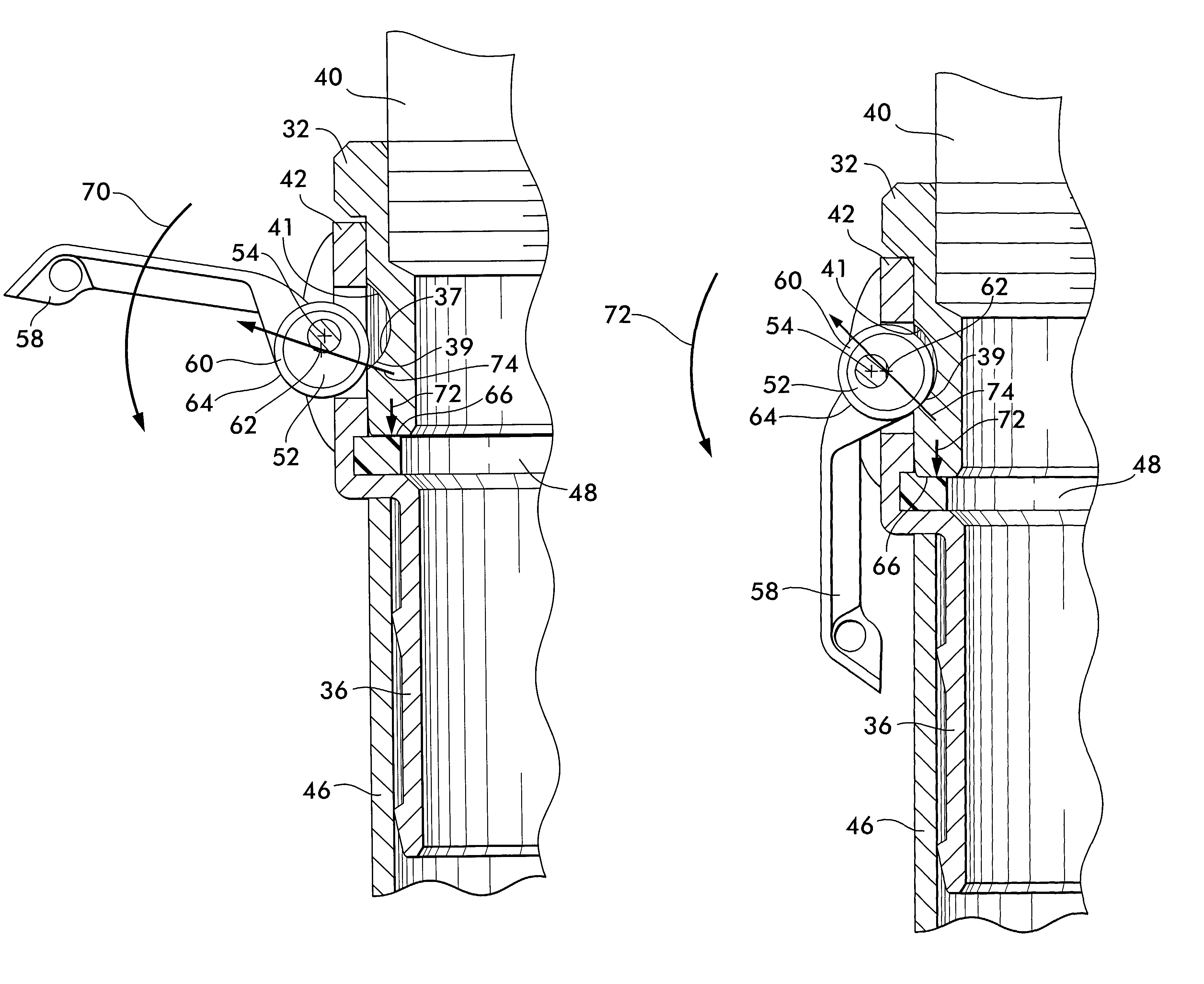
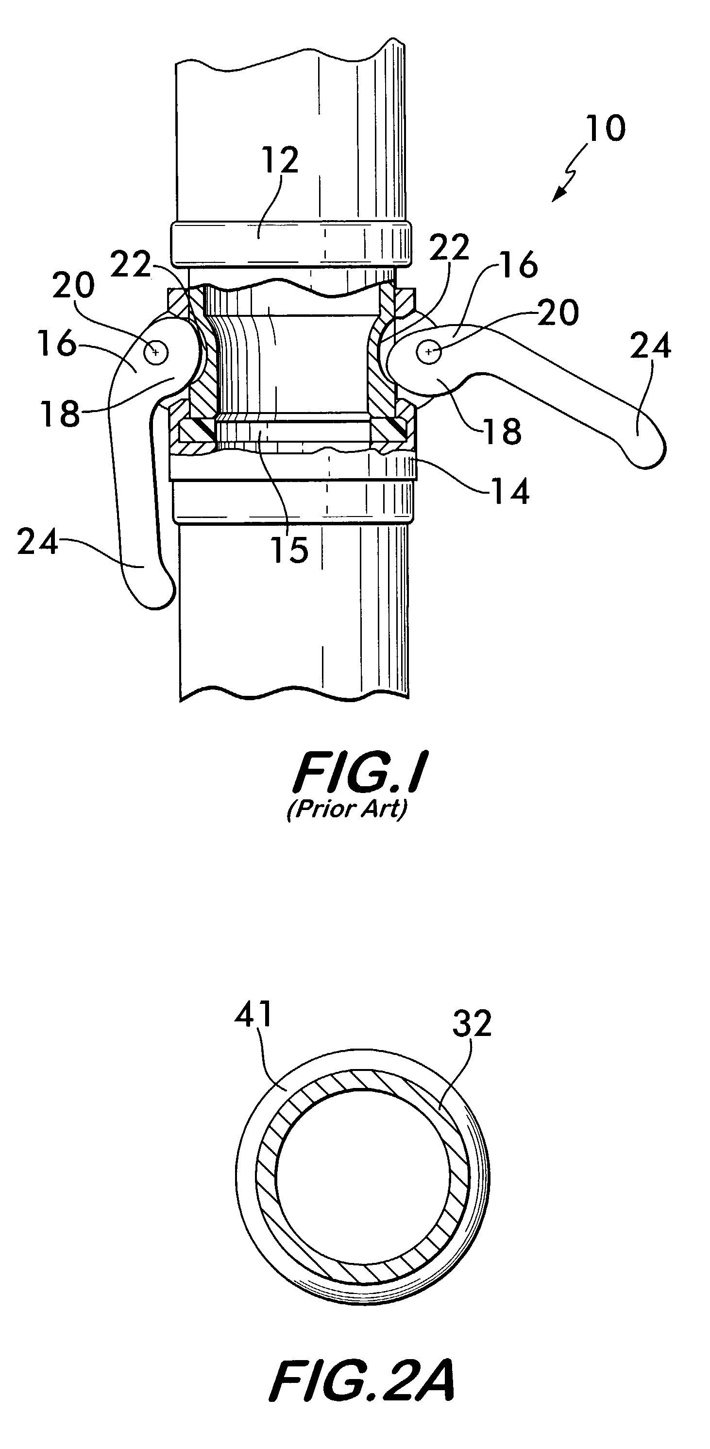
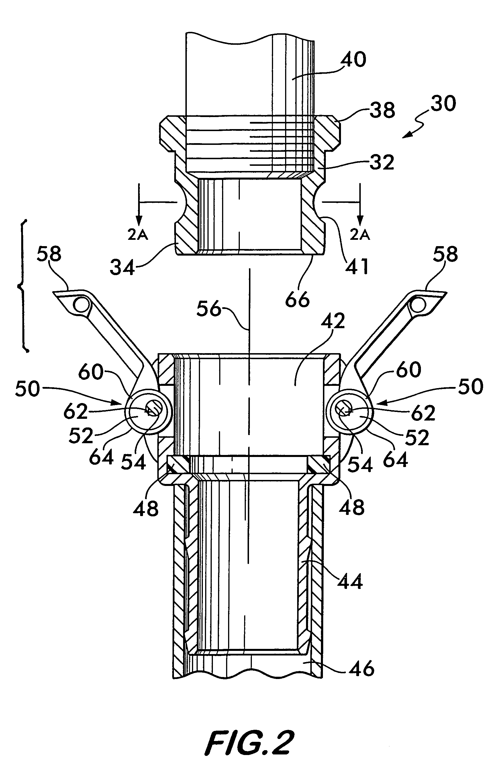
[0024]FIG. 2 shows a pipe coupling 30 according to the invention. Pipe coupling 30 includes a male fitting 32 having an end 34 adapted to engage a female fitting 36 and an opposite end 38 attachable to a conduit, for example a pipe or hose end 40. Male fitting 32 is preferably substantially cylindrical in shape and has a concave surface 41 positioned in spaced relation to end 34. Concave surface 41 faces radially outwardly and preferably extends circumferentially around the fitting as shown in FIG. 2A.

[0025]Female fitting 36 has a receptacle 42 at one end adapted to receive the male fitting 32. The other end 44 of the female fitting 36 is adapted to attach to another conduit, such as pipe or hose end 46. Preferably, a seal 48 is positioned within receptacle 42, the seal engaging both the male and female fittings to ensure a fluid-tight joint. Seal 48 is preferably formed from a flexible, resilient material such as an elastomer. Male and female fittings 32 and 36 are preferably machi...


PUM


Abstract

A coupling for joining conduits together is disclosed, the coupling having male and female fitting portions held in engagement by a self-locking roller cam positioned on the female portion. The roller cam has a cam body rotatable about an axis offset from the center of the cam body. An annular roller surrounds the cam body and is rotatable relatively to it. An outwardly facing surface on the roller engages an opposing concave surface on the male portion of the coupling. Reaction forces between the roller and the opposing surface operate along a line of action initially positioned to one side of the offset axis to create a torque opposing rotation of the cam into engagement with the opposing concave surface. Further forced rotation of the cam into engagement with the opposing concave surface causes the line of action of the reaction force to shift to an opposite side of the offset axis thereby creating a torque which causes rotation of the cam body into engagement with the opposing concave surface to retain the male fitting portion within the female fitting portion.

Description

RELATED APPLICATION[0001]This application is based on and claims the benefit of U.S. Provisional Application No. 60 / 356,232, filed Feb. 12, 2002.FIELD OF THE INVENTION[0002]The invention concerns a self-locking cam having a cam surface that rotates relatively to a cam body to reduce cam actuation force and wear between the cam and an opposing surface engaged by the cam surface. The invention is useful in quick disconnect pipe and hose couplings.BACKGROUND OF THE INVENTION[0003]In many industries such as mining, petroleum, construction and chemical production, as well as services such as municipal water and sewer service or emergency services, it is often advantageous to be able to rapidly construct temporary piping networks for the conveyance of pressurized fluids such as water, oil and natural gas. Since such piping networks must often be constructed in the field, with few construction facilities available, it is preferred that the piping comprising such networks be rapidly and sec...

Claims


Application Information

Patent Timeline
IPC IPC(8): F16L37/00F16L37/18
CPCF16L37/18
Inventor DOLE, DOUGLAS R.
Owner VICTAULIC
Why Eureka
Try Eureka