Combustion apparatus

a technology of combustion apparatus and combustion chamber, which is applied in the direction of lighting and heating apparatus, water heaters, air heaters, etc., can solve the problems of vibration combustion, noise increase, and disturbance of combustion balance, so as to reduce combustion noise and improve the stability of hot water supply performan

Active Publication Date: 2017-11-16
RINNAI CORP
View PDF6 Cites 8 Cited by
  • Summary
  • Abstract
  • Description
  • Claims
  • Application Information

AI Technical Summary

Benefits of technology

[0006]The present invention has been made in view of the foregoing problem, and an object of the present invention is to reduce combustion nois...

Problems solved by technology

As a result, combustion balance is disturbed, vibration combustion occurs, and noise increases.
Therefore, even a minute amount of drain may close the ventilation ports....

Method used


Image

  • Combustion apparatus
  • Combustion apparatus
  • Combustion apparatus

Examples


Embodiment Construction

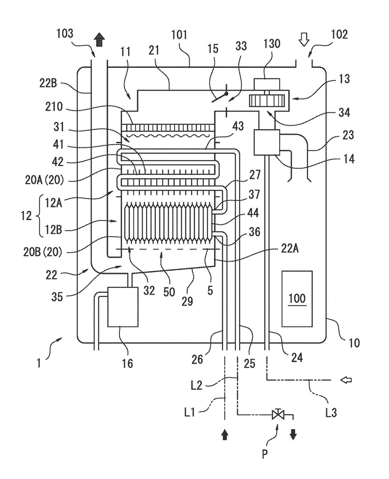
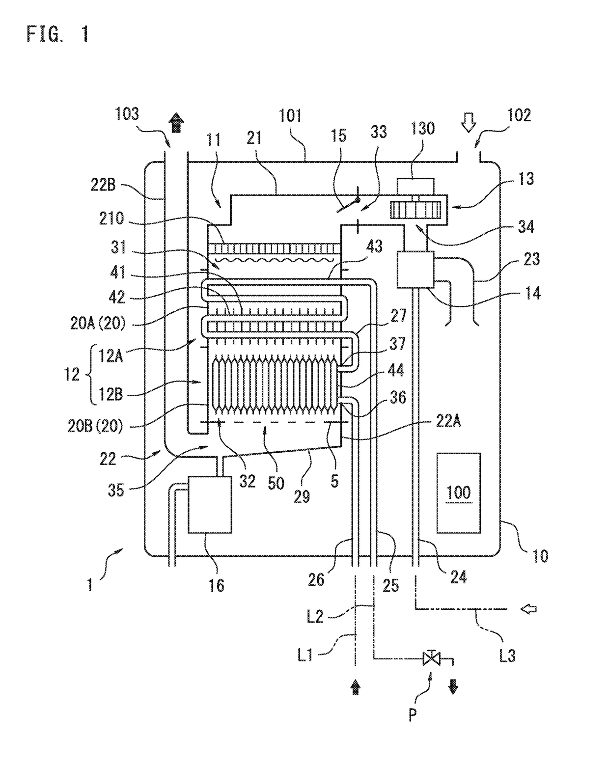
[0023]Hereinafter, referring to drawings, an embodiment of the present invention will be described in detail.

[0024]As shown in FIG. 1, a combustion apparatus 1 according to an embodiment of the present invention is a water heater that heats water (a heat medium) supplied into a heat exchanger 12 from a water supply pipe L1 with combustion exhaust gas generated by a burner 11, and supplies hot water to a hot-water supplying terminal P such as a faucet or a shower through a hot-water supply pipe L2.

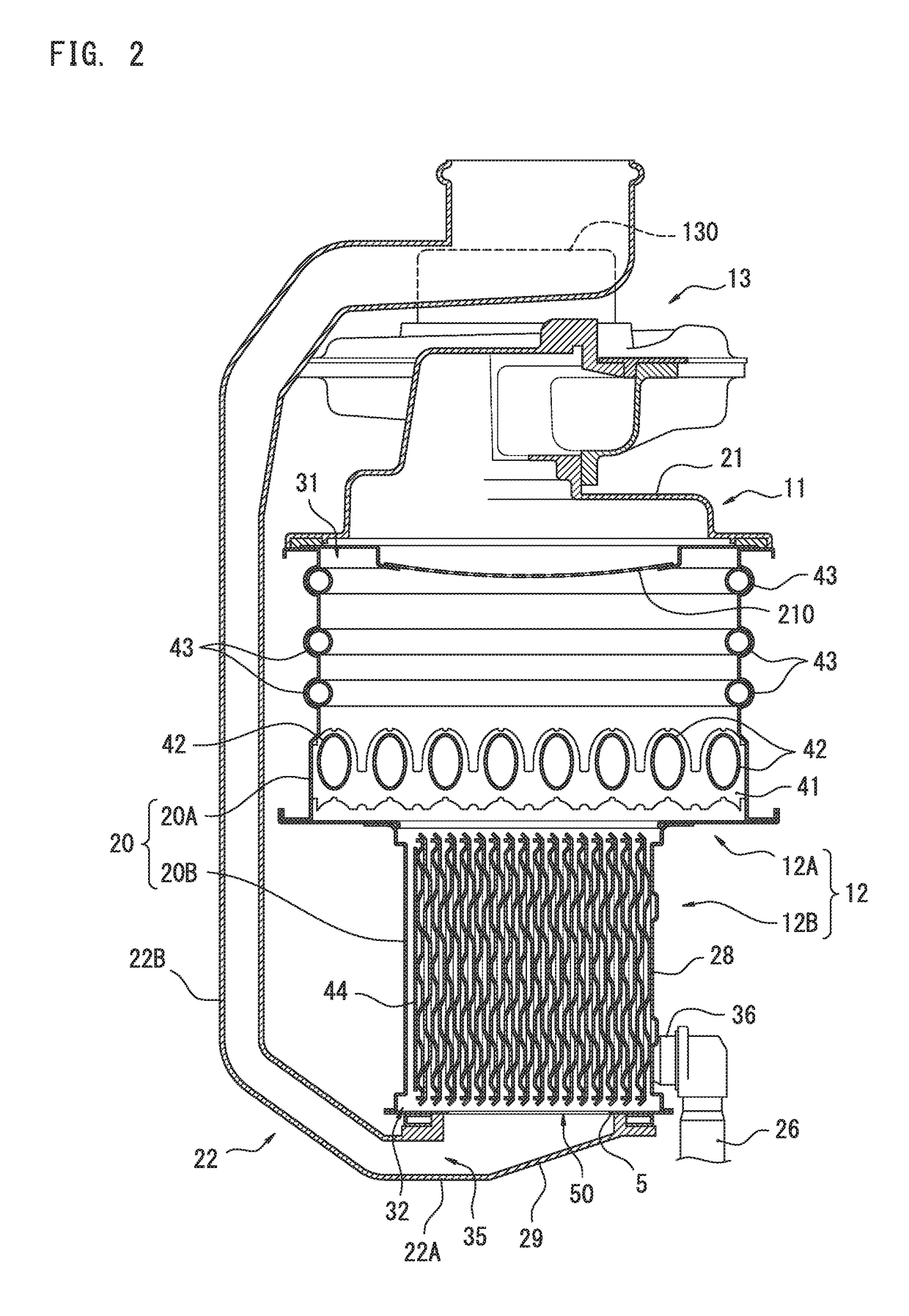
[0025]Inside an outer casing 10 of the combustion apparatus 1, a substantially quadrangular box shaped casing 20 forming an exterior of the heat exchanger 12 is accommodated. Accordingly, the casing 20 forms part of a circulation path of the combustion exhaust gas. At an upper wall 101 of the outer casing 10, an air supply port 102 for taking air outside the combustion apparatus 1 into the outer casing 10, and an exhaust port 103 for discharging the combustion exhaust gas introduced into th...


PUM


Abstract

A combustion apparatus includes a burner (11), a heat exchanger (12) accommodated in a casing (20), an exhaust passage (22B) provided to one side surface side of the casing (20), and an exhaust resistance member (5) having a plurality of ventilation ports (50) through which combustion exhaust gas passes, wherein at least one part of the ventilation ports (50) has an elongated hole shape extending in the flow direction of the combustion exhaust gas from beneath the casing (20) to the exhaust passage (22B).

Description

CROSS REFERENCE TO RELATED APPLICATIONS[0001]The present application claims a priority based on a Japanese Patent Application No. 2016-95805 filed on May 12, 2016, the content of which is hereby incorporated by reference in its entirely.FIELD OF THE INVENTION[0002]The present invention relates to a combustion apparatus. Especially, the present invention relates to a combustion apparatus configured to flow combustion exhaust gas generated by a burner through a heat exchanger from top to bottom.BACKGROUND ART[0003]According to a conventional combustion apparatus such as a conventional water heater or a conventional heat source device for a room heater, when airflow resistance in a circulation path of combustion exhaust gas ejected from a burner is too low, pressure around a combustion area of the burner largely fluctuates in an intensive combustion mode of the burner. As a result, combustion balance is disturbed, vibration combustion occurs, and noise increases. Accordingly, it has be...

Claims


Application Information

Patent Timeline
IPC IPC(8): F24H1/14F24H9/18F24H8/00
CPCF24H1/145F24H8/006F24H9/1881F24H9/0005F24H9/16F24H9/1836Y02B30/00F23C99/00F24H9/0026
Inventor MIURA, TAKUYA
Owner RINNAI CORP
Why Eureka
Try Eureka