
Fabric reinforced cement

a technology of reinforced cement and fiber cement, which is applied in the direction of transportation and packaging, synthetic resin layered products, chemistry apparatus and processes, etc., can solve the problems of degradation of fiberglass yarn used in reinforcement fabrics, lack of resistance to chemical attack from cement ingredients, etc., to reduce the degradation of reinforcement fabrics due to alkali attack, reduce reducing the effect of elongation

Active Publication Date: 2005-11-01
MILLIKEN & CO
View PDF6 Cites 24 Cited by
  • Summary
  • Abstract
  • Description
  • Claims
  • Application Information

AI Technical Summary

Benefits of technology

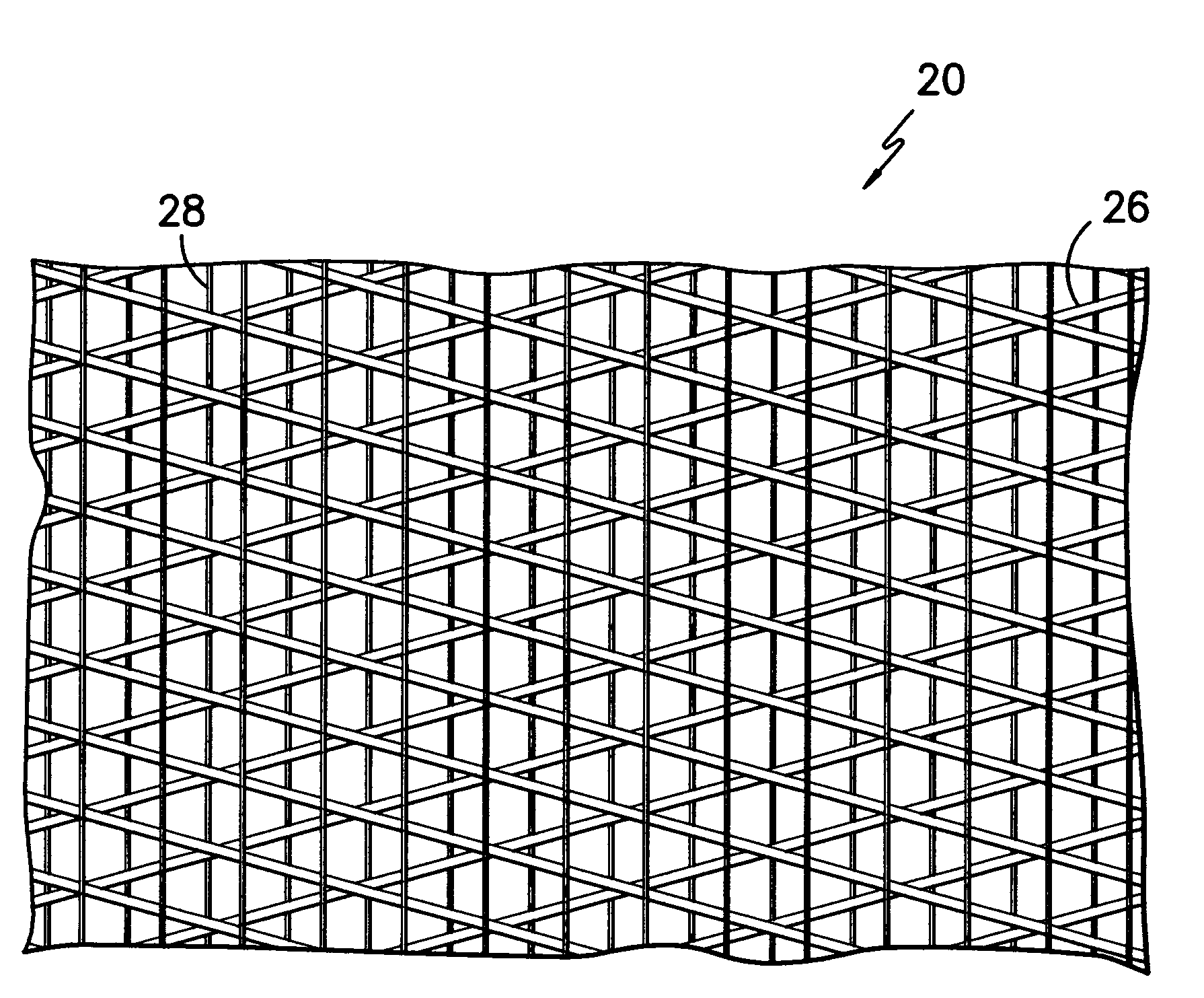
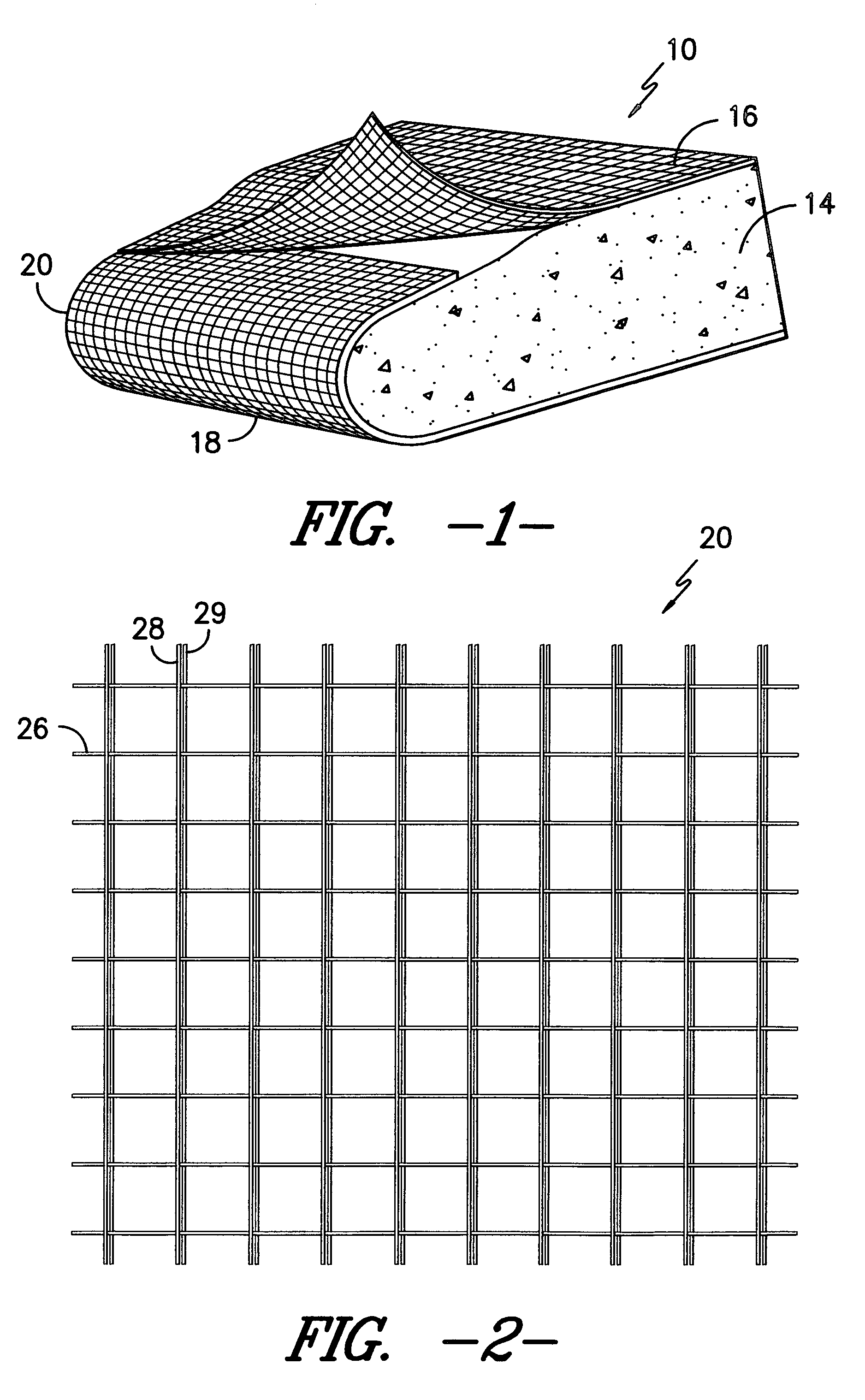
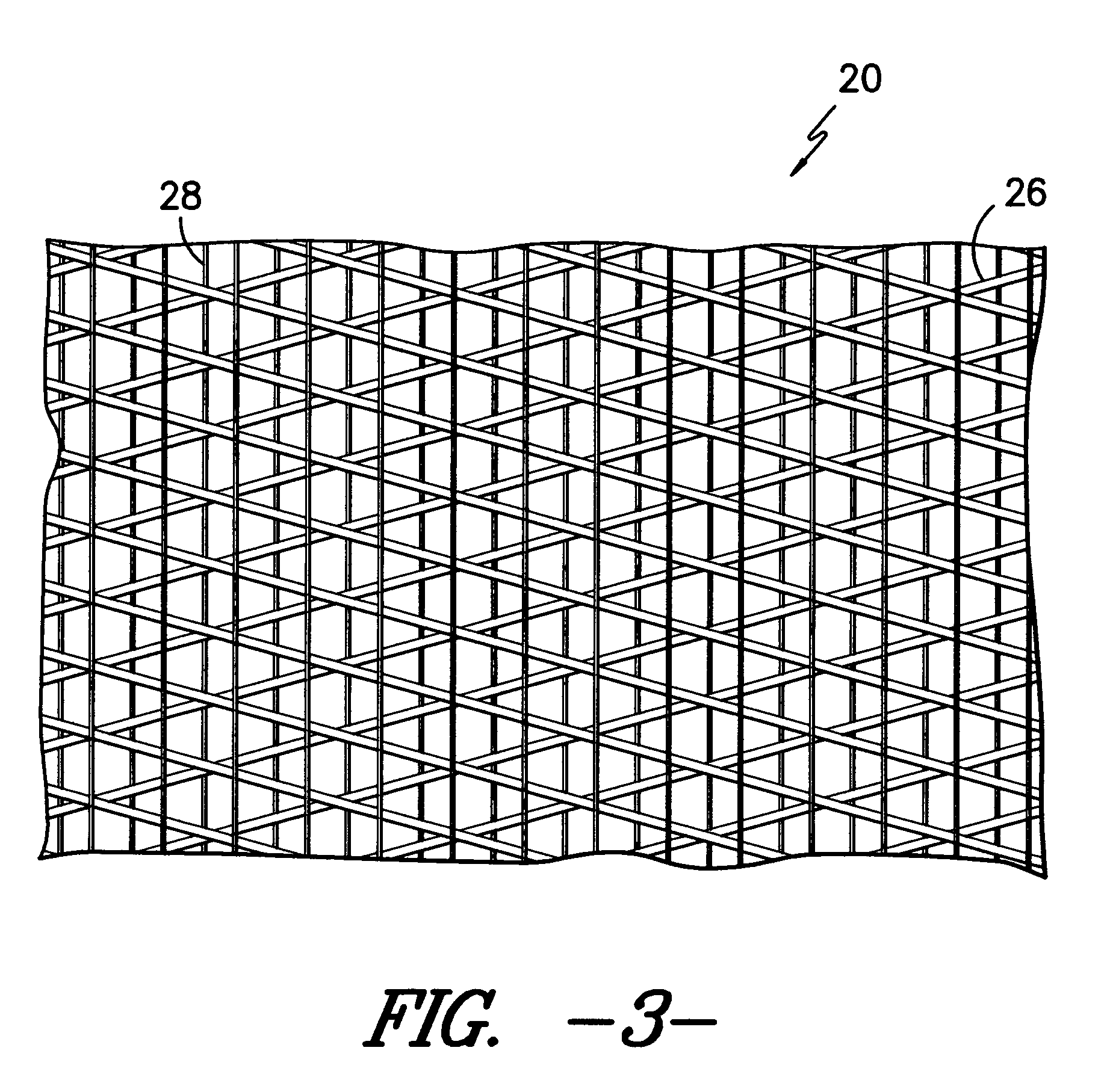
[0007]A feature of the present invention is the use of reinforcement fabric made of nucleated polypropylene fibers in combination with the cement panels. Not only does the use of nucleated polypropylene fibers minimize or altogether eliminate the need for a protective fabric coating, but also nucleated polypropylene possesses the same if not more beneficial features of other facing materials, such as fiberglass. Further, nucleated polypropylene breaks at higher elongations than fiberglass. Because the modulus of elasticity of nucleated polypropylene is similar to that of cement, the cement board or panel is less likely to fail for being too brittle, or too flexible. Polypropylene is also more resistant to alkali attack than fiberglass. Accordingly, the degradation of the reinforcement fabric due to alkali attack is reduced and the strength of the cement panel throughout its use is increased. Therefore, less nucleated polypropylene fiber needs to be employed in the reinforcement of the panels.
[0008]In addition, the nucleated polypropylene provides lower shrinkage yarns in comparison to non-nucleated polypropylene, which allows the yarns to maintain their high modulus characteristic better at elevated temperatures, such as those experienced during certain cement curing processes.

Problems solved by technology

Fiberglass, however, has a major disadvantage, which is its lack of resistance to chemical attack from the ingredients of the cements.
Common cements, such as Portland cement, provide an alkaline environment when in contact with water, and the fiberglass yarn that is used in reinforcement fabrics is degraded in these highly alkaline conditions.

Method used


Image

  • Fabric reinforced cement
  • Fabric reinforced cement
  • Fabric reinforced cement

Examples


example # 1

EXAMPLE #1

Monofilament

[0032]Nucleator concentrate (DMDBS) was made by mixing powdered nucleator with powdered PP resin with an MFI of 35 (Basell PDC1302) in a high speed mixer at a 10% concentration, extruded through a twin screw extruder at an extruder temperature of 240° C., and cut into concentrate pellets. The concentrates were let down into two PP resins: the first with an MFI of 12–18 g / 10 min (Exxon 1154) and the second with an MFI of 4 g / 10 min (Exxon 2252) at a level of 2.25% to give 0.225% (2250 ppm) nucleator concentration in the final polymer. This mixture, consisting of PP resin and the additive nucleator, was extruded using a single screw extruder through monofilament spinnerets with 60 holes. The PP melt throughput was adjusted to give a final monofilament denier of approximately 520 g / 9000 m. The molten strands of filament were quenched in room temperature water (about 25° C.), and then transferred by rollers to a battery of air knives, which dried the filaments. The...

example # 2

EXAMPLE #2

Monofilament

[0035]Nucleator concentrate (DMDBS and p-MDBS) was made by mixing powder phase nucleator with powdered PP resin with an MFI of 35 (Basell PDC1302) in a high speed mixer at a 10% concentration, extruded through a twin screw extruder at an extruder temperature of 240° C., and cut into concentrate pellets. The concentrates were let down into a homopolymer polypropylene resins with an MFI of 12–18 g / 10 min (Exxon 1154) at a level of 2.25% to give 0.225% (2250 ppm) nucleator concentration in the final polymer. This mixture, consisting of PP resin and the additive nucleator, was extruded using a single screw extruder through monofilament spinnerets with 40 holes. The PP melt throughput was adjusted to give a final monofilament denier of approximately 520 g / 9000 m. The molten strands of filament were quenched in room temperature water (about 25° C.), and then transferred by rollers to a battery of airs knives, which dried the filaments. The filaments, having been drie...

example # 3

EXAMPLE #3

Monofilament Yarn

[0038]Nucleator concentrate was made by mixing Millad powder with powdered polypropylene resin with a MFI of 35 in a high speed mixer at a 10% concentration, then extruded through a twin screw extruder at an extruder temperature of 240° C., and then cut into concentrate pellets. Concentrates were made of both Millad 3988 (DMDBS) and Millad 3940 (p-MDBS). These concentrates were let down into polypropylene resin with MFI 12–18 at a level of 2.2%, to give 0.22% (2200 ppm) nucleator concentration in the final polymer concentration. This yarn was extruded through a single screw extruder at a temperature of 490° F. and extruded through a dye into a water quench bath. The quenched fibers are wrapped over four sets of draw rolls and passed through three ovens in between them in order to draw the fiber and impart the final physical properties. The temperatures and roll speeds are given in the table below.

[0039]

TABLE #3Yarn Samples with Specific Nucleators AddedNuc...


PUM

PropertyMeasurementUnit
shrinkage rateaaaaaaaaaa
temperatureaaaaaaaaaa

Abstract

A cement panel that is reinforced with a fabric made of nucleated polypropylene fibers. The cement panel includes a core layer that is made of a lightweight cement composition. This core layer is covered with a layer of reinforcing nucleated polypropylene fabric on the top and on the bottom, each bonded to the core with a coating of cementitious material on the top and on the bottom of the core layer. On the edges of the cement panels, the fabric layers may be overlapped so as to augment the strength of these edges.

Description

BACKGROUND OF THE INVENTION[0001]The present invention relates generally to reinforced cementitious panels or boards, and, in particular, cementitious panels or boards that are reinforced with a fabric that is unaffected by alkali attack.[0002]The use of reinforced cement panels is well known in such industries as the ceramic tile industry. Generally, cement panels or boards contain a core formed of a cementitious material that is interposed between two layers of facing material. The facing materials employed typically share the features of high strength, high modulus of elasticity, and light weight so as to contribute flexural and impact strength to the high compressive strength but brittle material forming the cementitious core. Typically, the facing material employed with cement panels is fiberglass. Fiberglass performs particularly well in this application. Fiberglass provides greater physical and mechanical properties to the cement board. Fiberglass is also an efficient materia...

Claims


Application Information

Patent Timeline
Patent Type & Authority Patents(United States)
IPC IPC(8): B32B7/00D04H3/00E04C2/06
CPCE04C2/06Y10T428/24124Y10T428/24099Y10T428/24058Y10T428/24107Y10T428/249924Y10T428/249952
Inventor GRAHAM, SAMUEL E.ROYER, JOSEPH R.
Owner MILLIKEN & CO
Learn More