Curved belt support apparatus

a support device and belt technology, applied in the direction of conveyors, conveyor parts, transportation and packaging, etc., can solve the problems of shortening the useful life of the curved belt, difficult operation, and difficult operation

Inactive Publication Date: 2005-11-08
HABASIT AG
View PDF6 Cites 18 Cited by
  • Summary
  • Abstract
  • Description
  • Claims
  • Application Information

AI Technical Summary

Benefits of technology

[0018]Through the above construction, because the mounting and removal of the upper and lower arms to the

Problems solved by technology

Due to the high amount of contact pressure, the guide roller does not easily separate from the curved belt, making the operation difficult to perform.
When the curved belt is installed, the guide rollers must be put closer to the thick part of the curved belt while initial tension

Method used


Image

  • Curved belt support apparatus
  • Curved belt support apparatus
  • Curved belt support apparatus

Examples


Embodiment Construction

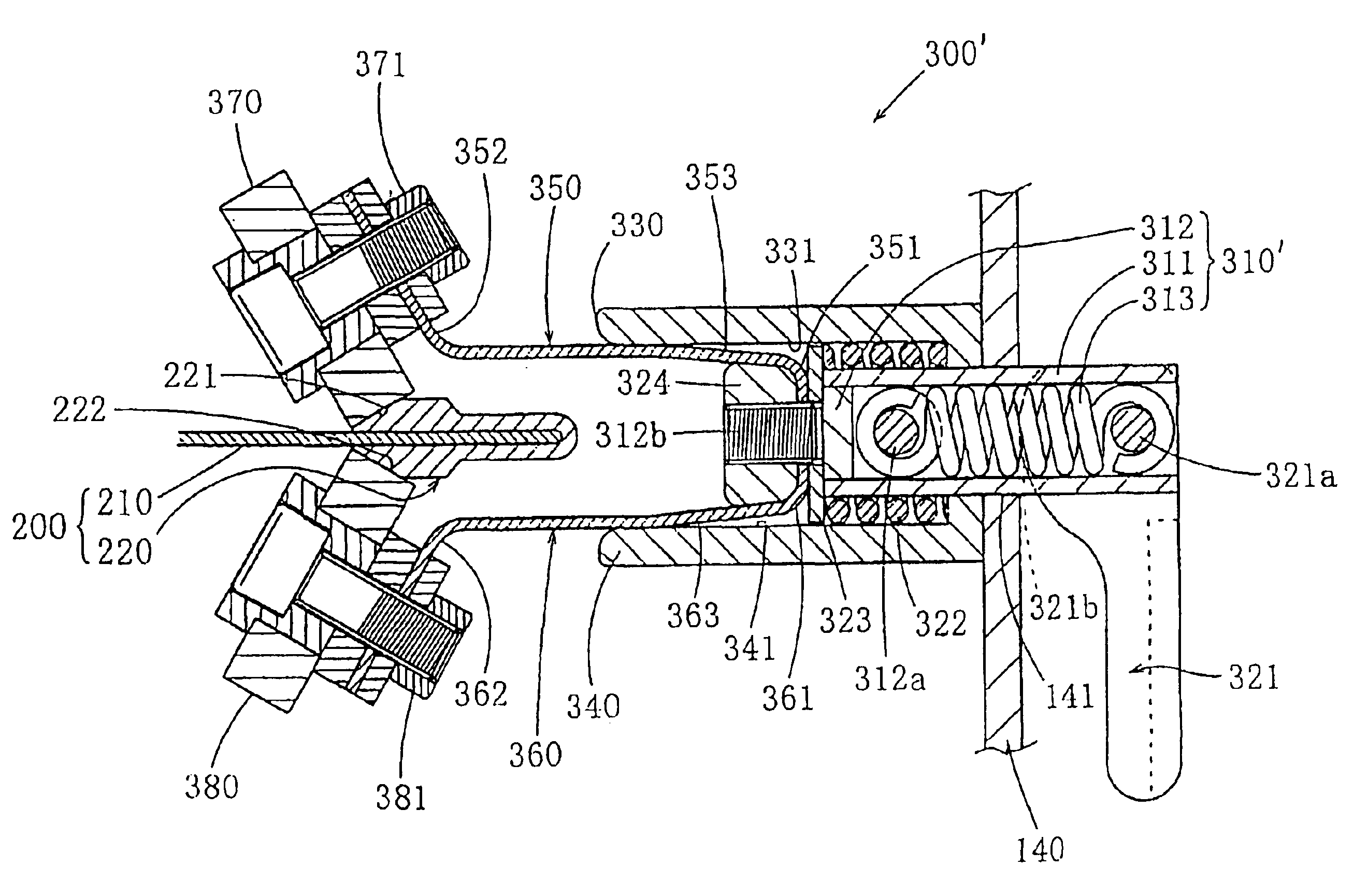
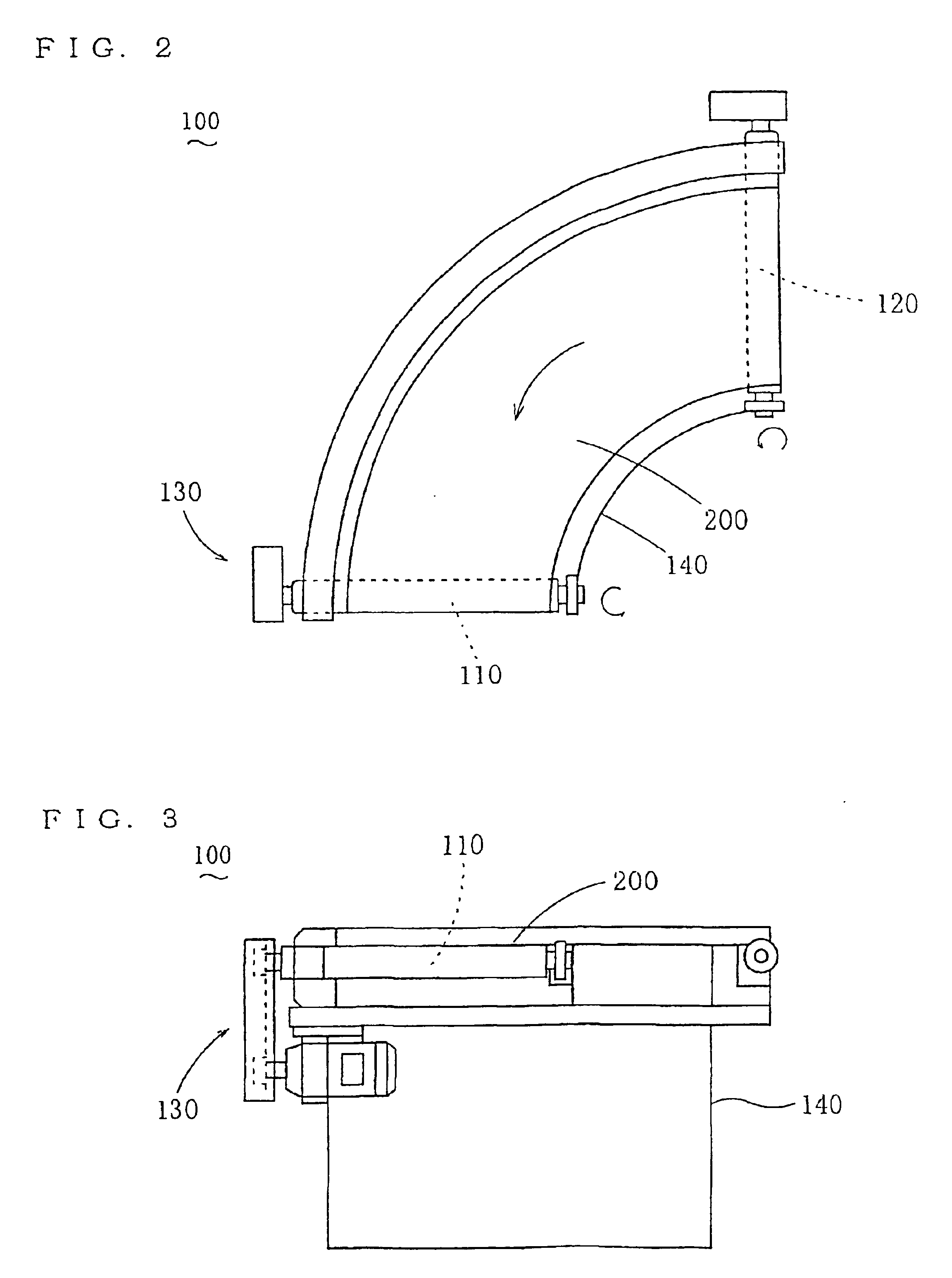
[0031]Embodiments of the curved belt support apparatus of the present invention will be explained below. FIGS. 1 through 3 show a curved conveyor 100 having a curved belt support apparatus of the first embodiment. In the drawings, 110 and 120 are conical or truncated conical or cylindrical rollers that rotate on an essentially horizontal axis and are angled relative to each other such that they form a V when viewed from above. A curved belt 200 is wound around these rollers 110 and 120. The curved belt 200 has a beveled configuration or a round configuration, or a beveled or round configuration with a hole therethrough. When the curved belt 200 is wound around the rollers 110 and 120, it forms a semi-circular conveyance surface when viewed from above. The rollers 110 and 120 rotate based on drive power from a drive mechanism 130 comprising an electric motor, a reduction mechanism, etc. and this rotation causes the curved belt 200 to revolve and advance the conveyance surface.

[0032]A...


PUM


Abstract

The invention provides a curved belt support apparatus (300) that prevents a curved belt (200) from moving inward by supporting a thick part (220) of the curved belt that thickens in both vertical directions at the outer edge of the belt. An upper roller (370) is brought in contact with the upper inside surface (221) of the thick part (220), a lower guide roller (380) is brought in contact with the lower guide roller (380) is brought in contact with the lower inside surface (222) of the thick part (200), and the upper and lower guide rollers are elastically supported such that they can move up and down. When operated, the upper guide roller (370) and the lower guide roller (380) are moved diagonally upward and downward, respectively, in the direction of the radial inner edge of the curved belt so that the thick part (220) of the belt is released from the upper and lower guide rollers.

Description

TECHNICAL FIELD[0001]The present invention pertains to the art related to a curved conveyor around which revolves a curved belt having a beveled configuration or a round configuration, or having a beveled or round configuration with a hole therethrough. The present invention relates to a support apparatus that supports a thick part of the curved belt at the outer edge thereof and prevents the belt from moving toward the inside edge.BACKGROUND ART[0002]Japanese Patent Kokai publication No. Heisei 5-24622 discloses a curved belt support apparatus comprising a base located outside the curved belt, in its radial direction, a bracket mounted to the base such that it can move vertically, a fixing means to fix the position of the bracket relative to the base in a prescribed position, and guide rollers rotatably mounted to the base and the bracket, respectively. The area near the thick part of the outer circumference of the curved belt is grasped by the guide rollers on the base side and th...

Claims


Application Information

Patent Timeline
IPC IPC(8): B65G15/00B65G15/60B65G15/62B65G15/02B65G21/16B65G39/16
CPCB65G15/00B65G15/02B65G15/62B65G2201/06
Inventor FUJIWARA, HIROAKIPOLT, WALTER NIKLAUS
Owner HABASIT AG
Why Eureka
Try Eureka