Vehicle seat

a vehicle seat and seat technology, applied in the field of vehicle seats, can solve the problems of restricting the application of vehicle seats, the vehicle seat may interfere with the steering wheel, and the vehicle seat type is rather difficult to use for the driver's seat, so as to achieve the effect of convenient entry and easy us

Inactive Publication Date: 2005-11-08
ARACO CORP
View PDF11 Cites 47 Cited by
  • Summary
  • Abstract
  • Description
  • Claims
  • Application Information

AI Technical Summary

Benefits of technology

[0007]It is an object of the present invention to teach a vehicle seat in which a user can easily get in and out of the driver's seat inside a vehicle cabin.
[0008]In the present invention, a seat is moved between a passenger seat position (a position where a seat other than the driver's seat is arranged, that is, an assistant driver's seat position or rear seat positions) and a driver's seat position by means of a long-sliding unit and is taken up and down via a door opening portion at the passenger seat position. Thus, no obstruction such as the steering wheel S is involved unlike the case in which the seat is moved at the driver's seat position. Therefore, a driver can move smoothly from the driver's seat position to the exterior of the vehicle or vice versa.
[0010]The passenger seat position that permits moving the seat between the interior and the exterior of the vehicle may be the assistant driver's seat position, the rear seat positions in a second row behind the driver's seat and a back door position. When the seat is moved at the rear position behind the driver's seat, it is preferable to use a longitudinal long-sliding unit. When the seat is moved at the assistant driver's seat position, it is preferable to use a lateral long-siding unit. When the seat is moved at the rear seat position behind the assistant driver's seat, it is preferably to use a combination of the lateral long-sliding unit and the longitudinal long-sliding unit. When the seat is moved at the rear seat position behind the assistant driver's seat, it is possible to use an oblique long-sliding unit. When the seat is moved by utilizing the oblique long-sliding unit, it is preferable to move the rear seat behind the driver's seat and the assistant driver's seat to retracted positions, thereby avoiding interference.
[0013]Next, for example, when the seat is moved via the door opening portion, the seat at the passenger seat position may have a height greater than that of the other seats in order to prevent the seat or the like from contacting the lower edge or the like of the door opening portion. If the seat with such a greater height is moved to the driver's seat, the person seated thereon (i.e., the driver) will be positioned at a high level (i.e., will have a high hip point). Therefore, it is preferable to provide a seat position adjusting unit that can adjust the height of the seat (hip point) at the driver's seat position.
[0014]When the seat is moved from the interior of the vehicle to the exterior of the vehicle, it is preferable that in the exterior of the vehicle, the height of the seat is set at a level as close to the ground as possible when in the exterior, so that the person seated thereon (the driver) may easily get in and out of the vehicle. Therefore, it is preferable that a seat moving device that has a four-bar linkage mechanism, a slide mechanism or other such mechanism is used as a seat moving device for moving the seat between the interior and the exterior of the vehicle. By using such a seat moving device, it is possible to reduce the height of the seat outside the vehicle by simply moving the seat from the interior of the vehicle to the exterior of the vehicle.
[0016]Further, it is preferable to use a connecting device that can separably connect the seat and the seat rotating device. In this case, by providing the seat with wheels, the seat can be used as a wheelchair when it is separated from the rotating device outside the vehicle. Further, because the person seated on the seat can move between the interior and the exterior of the vehicle while remaining seated thereon, it is easy for the seated person to move.

Problems solved by technology

However, this type of conventional vehicle seat is rather difficult to use for a driver's seat.
Therefore, such a vehicle seat is restrictively applied to an assistant driver's seat and a rear seat (i.e., the seats other than the driver's seat).
One of the reasons for this is that if this type of vehicle seat is applied to the driver's seat, the vehicle seat may interfere with the steering wheel when the seat unit moves between the interior and the exterior of the vehicle cabin.

Method used


Image

  • Vehicle seat
  • Vehicle seat
  • Vehicle seat

Examples


first embodiment

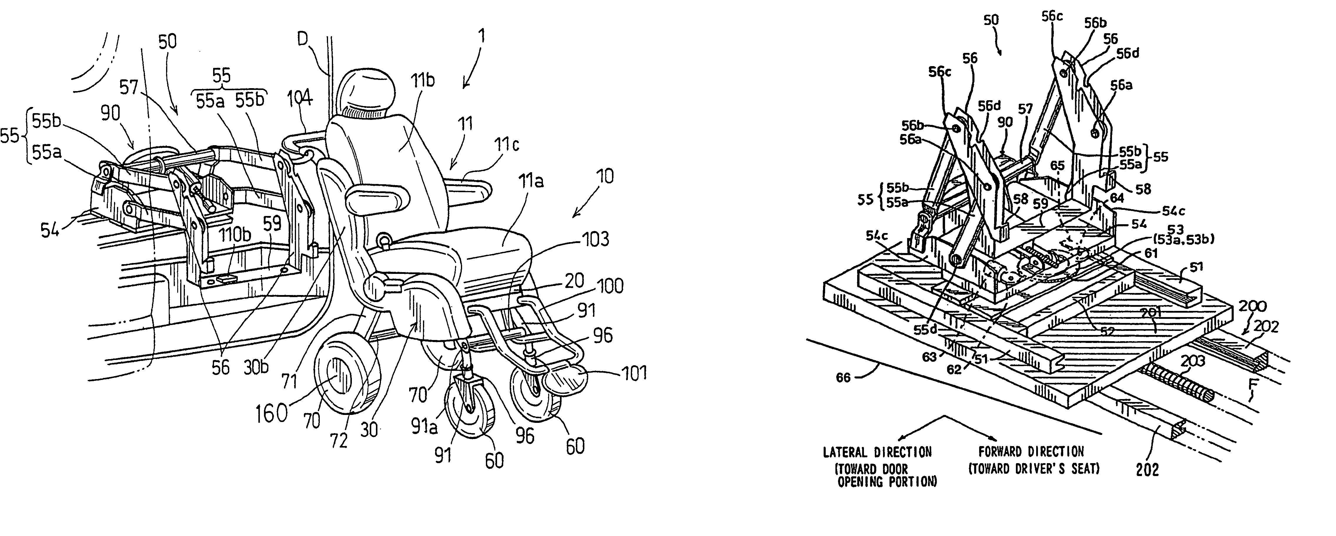
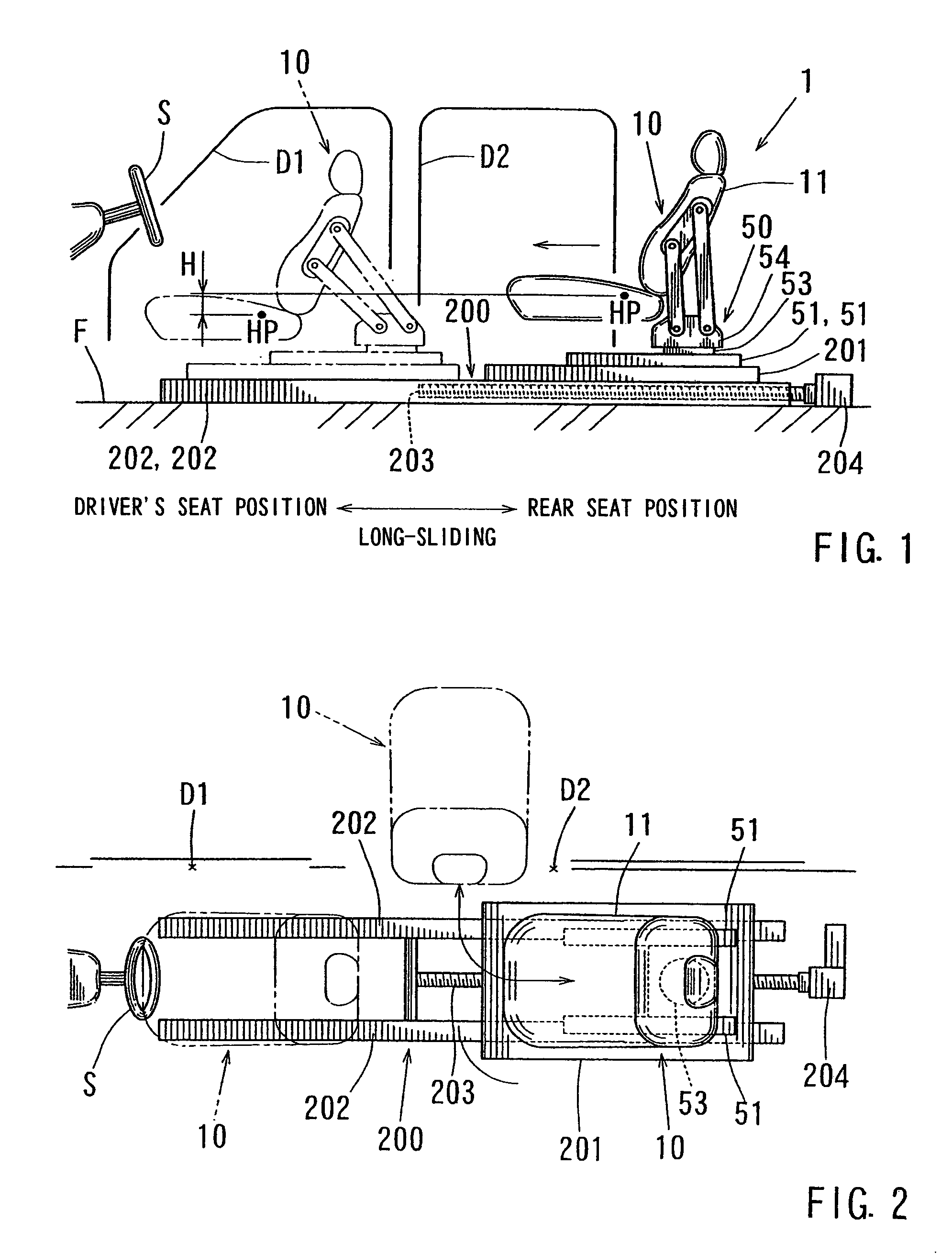
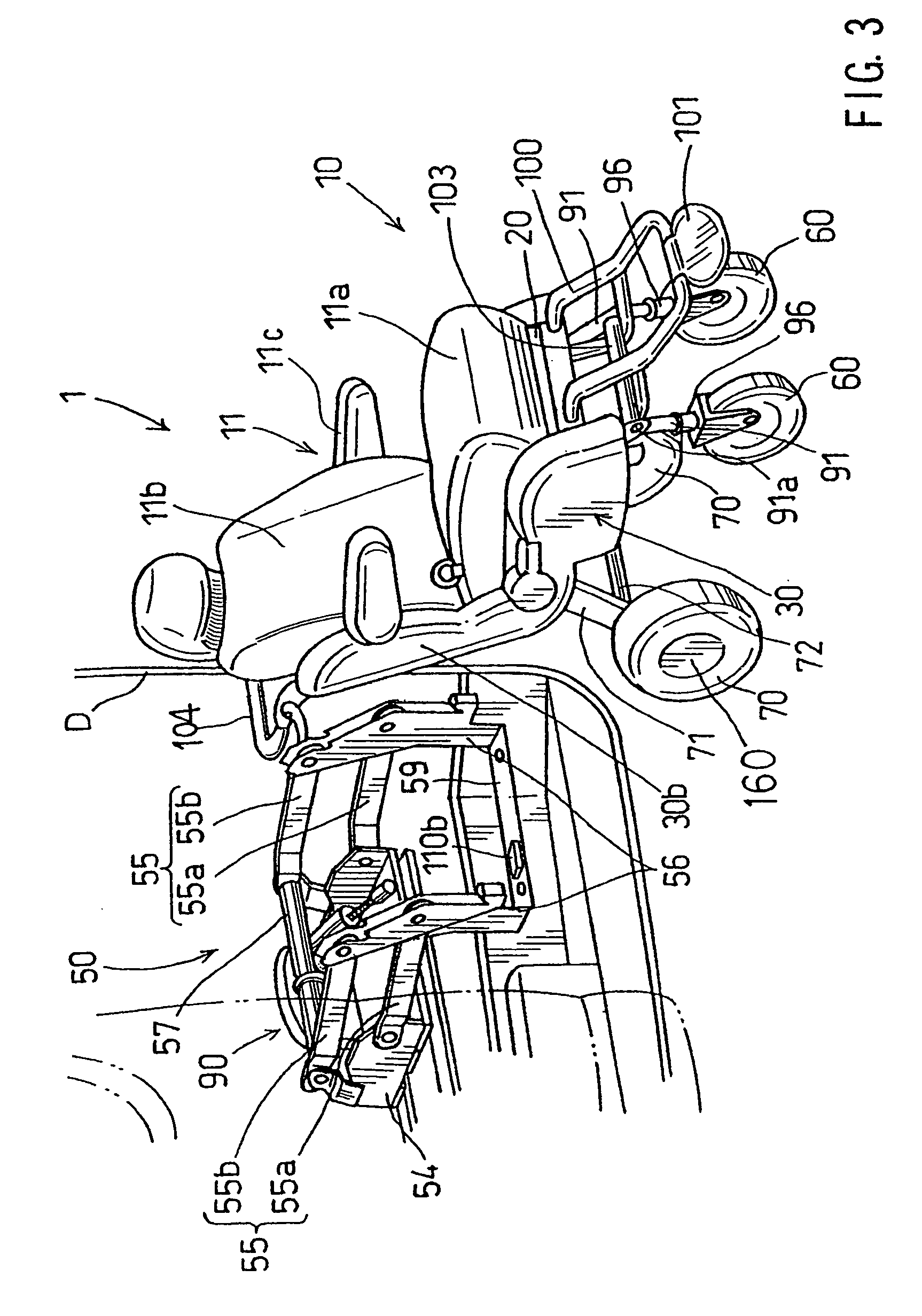
[0037]the present invention will now be described with reference to FIGS. 1 to 10. FIGS. 1 and 2 show a vehicle seat 1 according to this embodiment. This vehicle seat 1 is a seat that is used as a driver's seat. The vehicle seat 1 has a seat unit 10, a lift-up unit 50 and a long-sliding unit 200. The lift-up unit 50 serves to move the seat unit 10 from the interior of a vehicle cabin to the exterior of the vehicle cabin or vice versa. The long-sliding unit 200 serves to move the seat unit 10 over a relatively long distance between a rear seat position behind the driver's seat and a driver's seat position (long-sliding).

[0038]In FIGS. 1 and 2, the seat unit 10 that is positioned at the rear seat position behind the driver's seat is indicated by solid lines, and the seat unit 10 that is positioned at the driver's seat position is indicated by chain double-dashed lines. In the following description, a seat position in which a driver sits will be referred to as “a driver's seat position...


PUM


Abstract

A vehicle seat 1 includes a seat unit, a lift-up unit and a long-sliding unit. The lift-up unit moves the seat unit between an interior and an exterior of a vehicle via a door opening portion that corresponds to a passenger seat position. The long-sliding unit moves the seat unit between a driver's seat position and the fellow passenger seat position. The lift-up unit moves the seat unit downward when the seat unit is positioned at the driver's seat position, so that the seat unit is located at a suitable position for driving.

Description

RELATED APPLICATIONS[0001]This application is a continuation of U.S. application Ser. No. 10 / 468,240 filed Mar. 3, 2004, now abandoned, which is a 371 of PCT Application No. PCT / JP01 / 08863 filed Oct. 9, 2001, which claims priority to Japan Application No. 2001-044065 filed Feb. 20, 2001, each hereby incorporated by reference.TECHNICAL FIELD OF THE INVENTION[0002]This invention relates to a vehicle seat. More particularly, this invention relates to a vehicle seat that enables an elderly person, a physically handicapped person or other such persons to easily get into and out of the vehicle.BACKGROUND OF THE INVENTION[0003]A known vehicle seat for a welfare vehicle is disclosed in JP 11-309175 A. This vehicle seat has a seat unit and a lift-up unit. The seat unit has a seat main body and foldable front and rear wheels. The lift-up unit is installed in the interior of a vehicle cabin and capable of moving the seat unit between the interior and the exterior of the vehicle cabin, with the...

Claims


Application Information

Patent Timeline
Patent Type & Authority Patents(United States)
IPC IPC(8): A61G3/00A61G3/06B60N2/24A61G7/10
CPCB60N2/245A61G3/062A61G5/045A61G7/1017A61G7/1059A61G7/1076Y10S414/134B60N2/04
Inventor TAKENOSHITA, TADASHISUEHIRO, YOSHIROUKURODA, TOMOYUKINARUSE, TEIJISUZUKI
Owner ARACO CORP
Why Eureka
Try Eureka