Non-rotatable protective member, cutting tool using the protective member, and cutting tool assembly using the protective member

a protective member and non-rotatable technology, applied in cutting tools, earthwork drilling and mining, slitting machines, etc., can solve the problems of long useful life of cutting tools, increased wear of the forward face of the holder, and increased tool wear

Active Publication Date: 2005-11-08
KENNAMETAL INC
View PDF18 Cites 79 Cited by
  • Summary
  • Abstract
  • Description
  • Claims
  • Application Information

AI Technical Summary

Problems solved by technology

As can be appreciated these rotatable cutting tools and the holders operate in a severe environment that causes wear on these components, as well as other possible failures due to the severity of the operating conditions.
While it is inevitable that the cutting tools experience wear, the ability of the cutting tool to rotate about its central longitudinal axis during operation generally prolongs the useful life of the cutting tool.
One factor that influences the milling pattern is the degree of wear that is suffered by the forward face of the holder.
While at least at the beginning of a milling cycle, the structure disclosed in U.S. Pat. No. 6,508,516 would be expected to provide a non-rotatable washer; however, over time the structure may be susceptible to problems.
One such problem is that the groove that engages the tab may become clogged with debris.
Obviously, this condition could compromise the integrity of the connection between the tab and the groove and result in the loss of the non- rotatable feature of the washer.
Another problem is that over the course of operation the tab is exposed along the side of the tool so as to be susceptible to wearing away.
The erosion of the tab could compromise the integrity of the connection between the tab and the groove and result in the loss of the non-rotatable feature of the washer.

Method used


Image

  • Non-rotatable protective member, cutting tool using the protective member, and cutting tool assembly using the protective member
  • Non-rotatable protective member, cutting tool using the protective member, and cutting tool assembly using the protective member
  • Non-rotatable protective member, cutting tool using the protective member, and cutting tool assembly using the protective member

Examples


Embodiment Construction

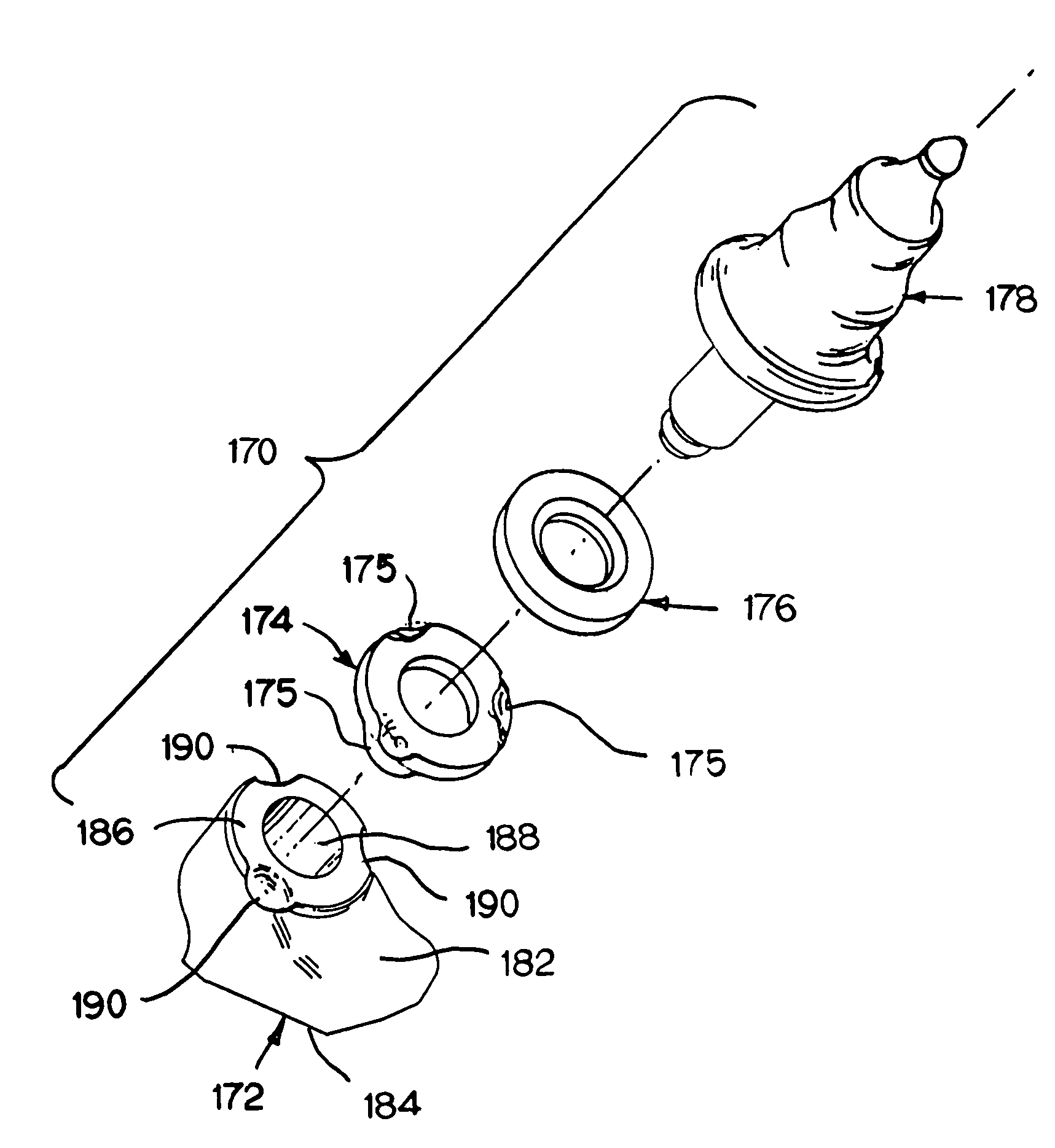
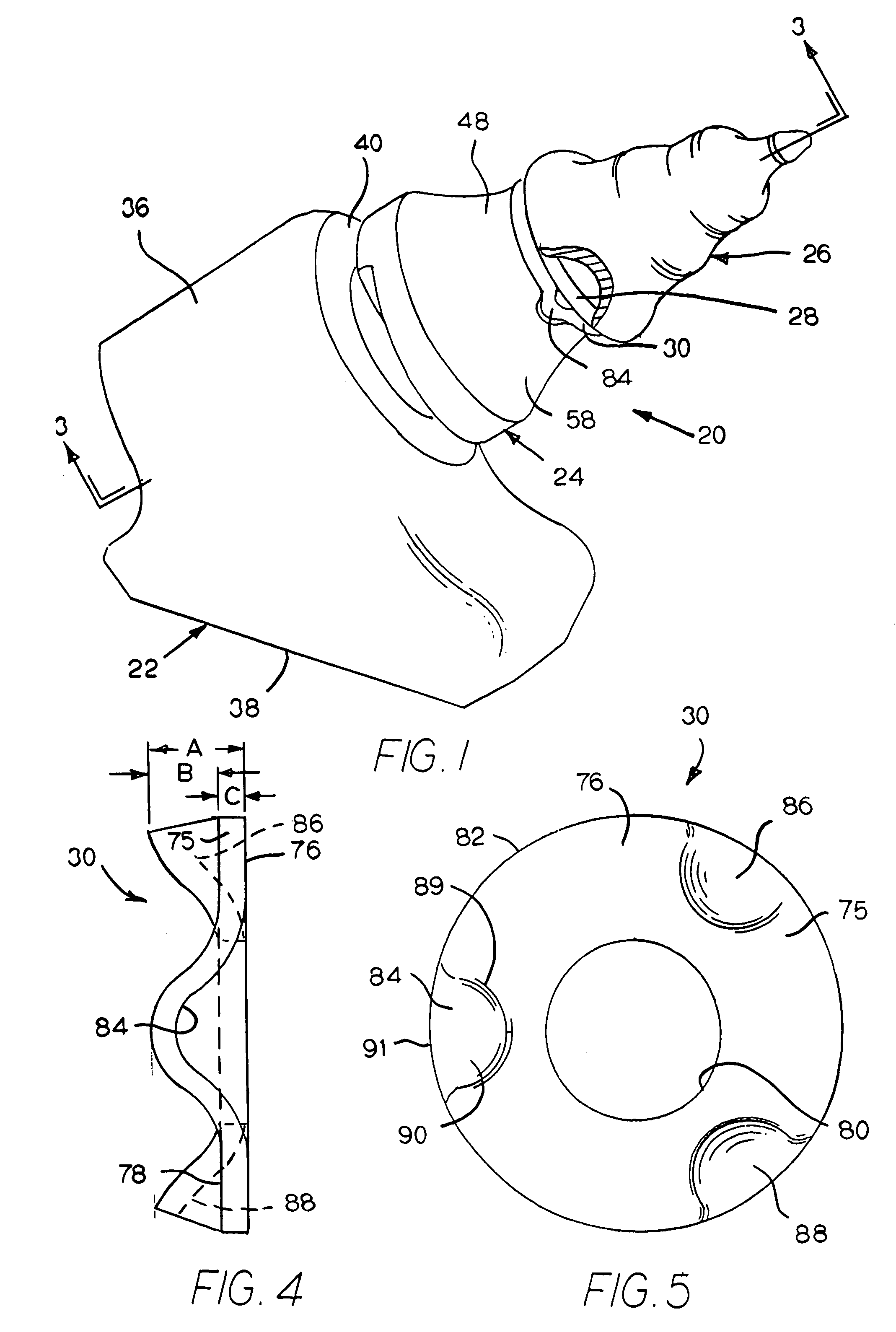
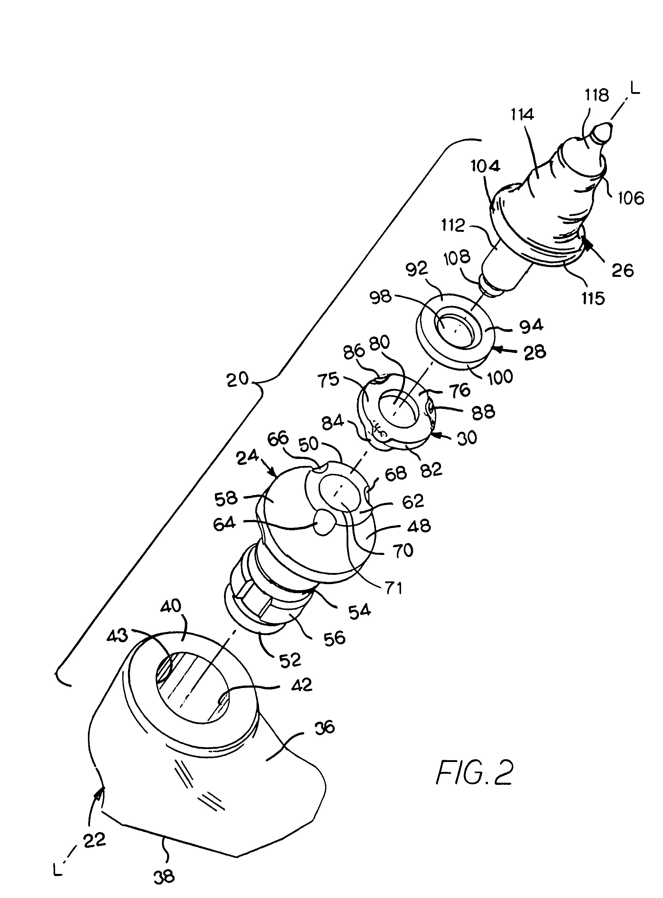
[0031]Referring to the drawings, FIG. 1 illustrates a first embodiment of a cutting tool assembly useful for generating cutting debris upon impinging the earth strata, and generally designated as 20. Cutting tool assembly 20 includes a holder 22 that is affixed to a driven member (not illustrated) such as, for example, a wheel, a chain or a drum as in the case of a road milling machine that may be used to mill the surface of an asphaltic roadway. The cutting tool assembly 20 further includes a sleeve 24 that, as described in more detail hereinafter, is retained within the central bore of the block 22. The cutting tool assembly 20 also includes a rotatable cutting tool 26 that carries a flat washer 28 and a non-rotatable washer 30. The rotatable cutting tool is rotatable retained within the bore of the sleeve 24. A portion of the cutting tool 26 is broken away in FIG. 1 so as to be able to illustrate the flat washer 28 and the non-rotatable washer 30. FIG. 1 shows these components of...


PUM


Abstract

A cutting assembly that includes a block that has a body that contains a block bore. A sleeve has a body that contains a bore that has an axial forward end and a forward surface surrounding the bore at the axial forward end thereof. The sleeve further contains at least one scallop beginning at extending in an axial rearward direction from the forward surface. There is a cutting tool rotatably contained within the bore of the sleeve. There is a non-rotatable washer that has a washer body that has a peripheral edge wherein the washer body contains at least one indention adjacent to peripheral edge. The indention of the non-rotatable washer is received within the scallop.

Description

BACKGROUND OF THE INVENTION[0001]The present invention pertains to a protective member (e.g. a washer-like member) alone, a rotatable cutting tool that uses the protective member, as well as a cutting tool assembly that uses the protective member. More particularly, the invention pertains to a non-rotatable protective member (e.g., a non-rotatable washer) alone, a rotatable cutting tool that uses the non-rotatable protective member, as well as a cutting tool assembly that uses the non-rotatable protective member wherein the cutting tool assembly includes a cutting tool and a holder for the cutting tool wherein the cutting tool carries the non-rotatable protective member that engages the holder so as to be non-rotatable.[0002]One typical use of a rotatable cutting tool is in conjunction with a machine used to break up (or cut) a substrate such as earth strata (e.g., coal, the ground, asphalt pavement, asphaltic concrete, concrete or the like). In its very basic aspects, such a machin...

Claims


Application Information

Patent Timeline
Patent Type & Authority Patents(United States)
IPC IPC(8): E21C25/10E21C25/00E21C37/00E21C35/18E21C35/197
CPCE21C35/197E21C2035/1826E21C35/188
Inventor MOUTHAAN, DANIEL J.
Owner KENNAMETAL INC
Why Eureka
Try Eureka