Barrel polishing device

a barrel and polishing technology, which is applied in the direction of polishing machines, metal-working equipment, manufacturing tools, etc., can solve the problems of interference between the flow of the polishing media stored in the back side of the workpiece and the baffle, and achieve the effect of increasing the surface pressure of the polishing media with respect to the back side at the lower part of the workpi

Inactive Publication Date: 2005-11-08
BBF YAMATE
View PDF8 Cites 24 Cited by
  • Summary
  • Abstract
  • Description
  • Claims
  • Application Information

AI Technical Summary

Benefits of technology

[0015]If the baffle member is placed in the vicinity of a lower part of the back side of the workpiece, the flow of the polishing media stored in a lower side of the back side of the workpiece is interfered with the baffle. As a result, the surface pressure of the polishing media with respect to the back side at the lower part of the workpiece can be increased.

Problems solved by technology

Accordingly, the flow of the polishing media stored in the back side of the workpiece is interfered with the baffle.

Method used


Image

  • Barrel polishing device
  • Barrel polishing device
  • Barrel polishing device

Examples


Embodiment Construction

[0022]In the embodiments to be described hereinafter, a “vehicle wheel” will be employed as one example of a workpiece.

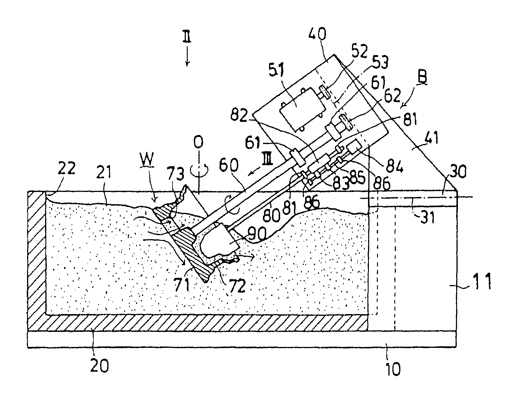
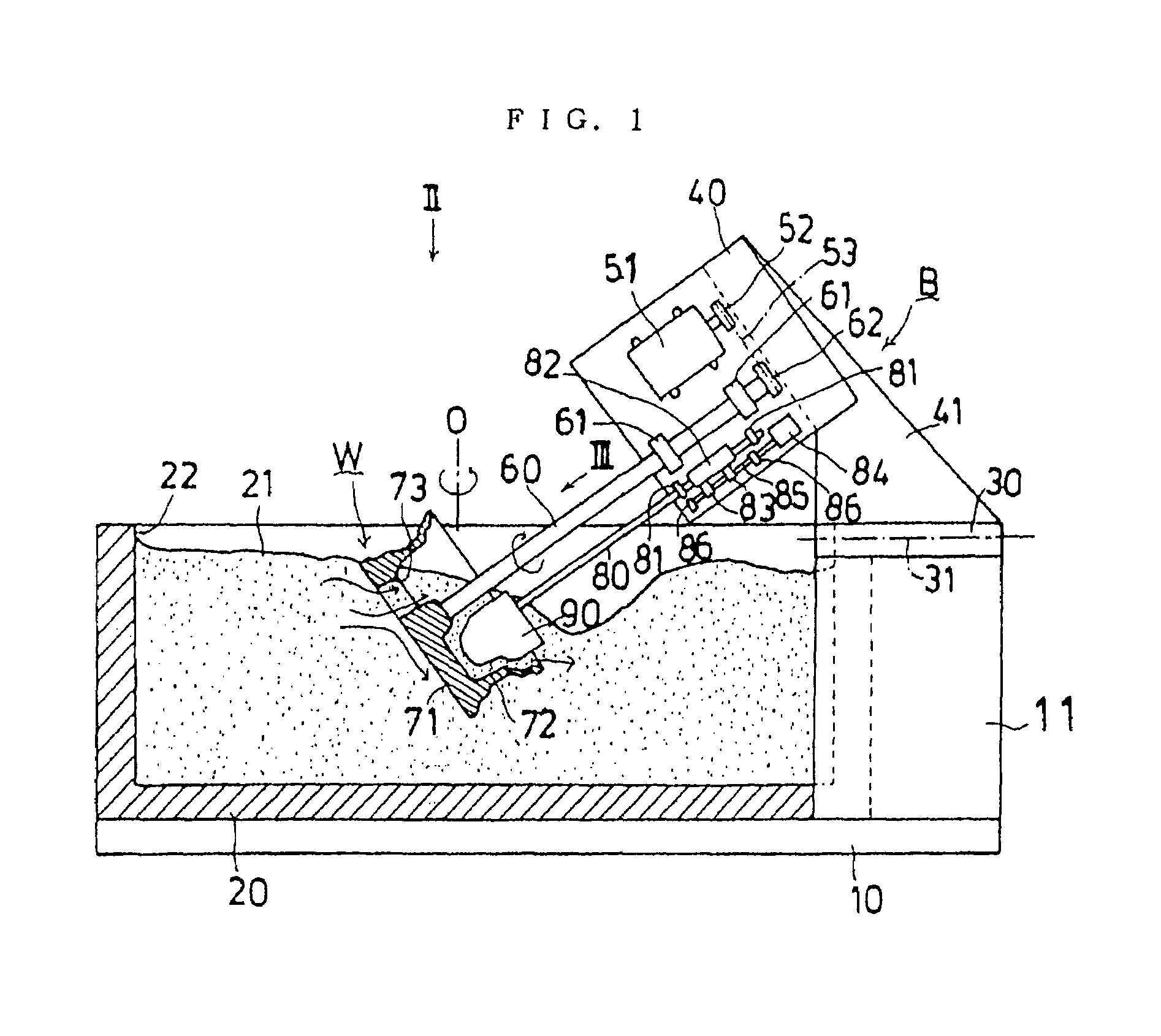
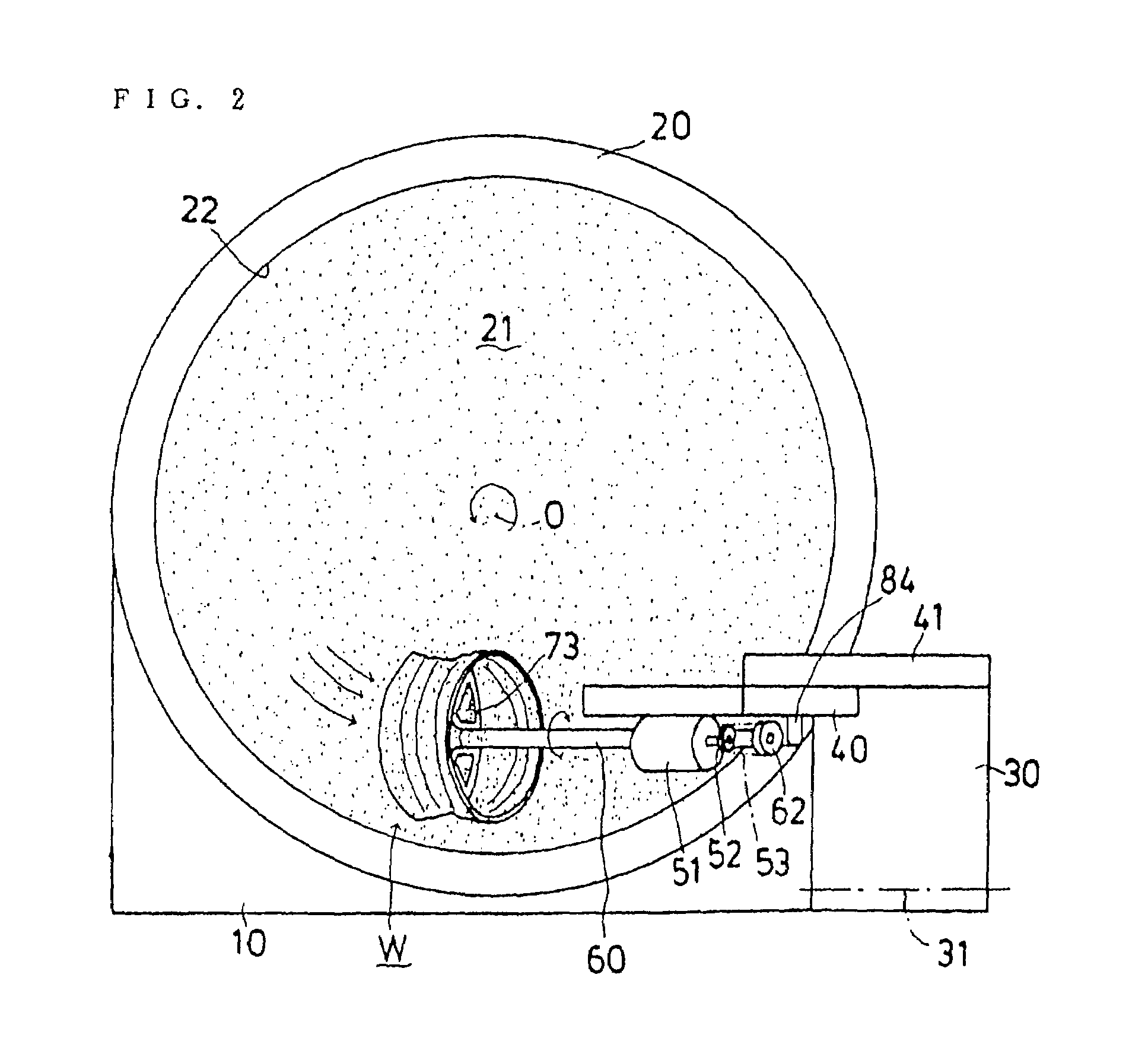
[0023]FIG. 1 is a sectional view of a barrel polishing device according to one embodiment of the present invention, FIG. 2 is a view when viewed in a direction as indicated by an arrow II of FIG. 1, FIG. 3 is a view when viewed in a direction as indicated by an arrow III of FIG. 1, FIG. 4 is a sectional view taken on line IV—IV of FIG. 3, and FIG. 5 is a view like FIG. 1 but showing another embodiment of the present invention.

[0024]In FIGS. 1 and 2, reference symbol B denotes a barrel polishing device and 10 denotes its base. Reference numeral 20 denotes a polishing media storage tank which is mounted on the base 10. This polishing media storage tank 20 is in the shape of a circular cylinder. The polishing media storage tank 20 is turnable in a peripheral direction about an axis O by an appropriate turning means (see an arrow of FIG. 1, indicating the turning direct...


PUM


Abstract

A barrel polishing device for polishing a workpiece having a relatively complicated shape such as a vehicle wheel. The barrel polishing device comprises a polishing medium storage tank for storing polishing media, a base, a workpiece supporting shaft mounted on the base, and a workpiece detachably mounted on a tip part of the workpiece supporting shaft, the polishing media stored in the polishing medium storage tank being flowed by an appropriate means, and the workpiece supporting shaft being disposed so that a front side of the workpiece opposes the flow of the polishing media, the workpiece supporting shaft being rotated about an axis thereof, and a baffle member being placed in the vicinity of a back side of the workpiece.

Description

TECHNICAL FIELD[0001]This invention relates to a barrel polishing device which is used for barrel polishing, for example, a vehicle wheel.BACKGROUND ART[0002]Conventionally, when a vehicle wheel is to be barrel polished, it was an ordinary practice that the front side of the vehicle wheel is arranged in such a manner as to oppose to the flow of polishing media in the state slanted forward, and the side of the vehicle wheel is polished by flowing the polishing media along the front side of the vehicle wheel while rotating the vehicle wheel (about the axis).[0003]The polishing media, which have polished the front side, are turned from the perimeter of the vehicle wheel and stored in the back.[0004]In this conventional barrel polishing method, however, the back of the vehicle wheel is difficult to polish because the polishing media stored in the back side of the vehicle wheel are flown away backward while turning by the turning force of the vehicle wheel.[0005]It is, therefore, an obje...

Claims


Application Information

Patent Timeline
Patent Type & Authority Patents(United States)
IPC IPC(8): B24B19/00B24B31/00
CPCB24B31/003
Inventor KAWASAKI, SHUJIOTANI, NAOMICHIYAMAGUCHI, KAZUOYOKOYAMA, AKIRA
Owner BBF YAMATE
Why Eureka
Try Eureka