Laser gun and shooting system for the same

Inactive Publication Date: 2005-11-08
NEC CORP
View PDF9 Cites 15 Cited by
  • Summary
  • Abstract
  • Description
  • Claims
  • Application Information

AI Technical Summary

Benefits of technology

[0011]Another object of the present invention is to provide a laser gun that can emit a laser beam bullet safely, and a shooting box, a target box, and a laser gun shooting system using the laser gun and the shooting box.
[0012]Another object of the present invention is to provide a laser gun, a t

Problems solved by technology

However, there is a limitation on improvements in determination precision of a shot position in a shooting system using the flash light gun.
In the laser gun connected with a computer by an electric wire cable, the wire cable affects the shooter's sense which has become very sharp, and hinders mental stability and

Method used


Image

  • Laser gun and shooting system for the same
  • Laser gun and shooting system for the same
  • Laser gun and shooting system for the same

Examples


Embodiment Construction

[0047]Hereinafter, a laser gun and a shooting system using the same of the present invention will be described below in detail with reference to the attached drawings.

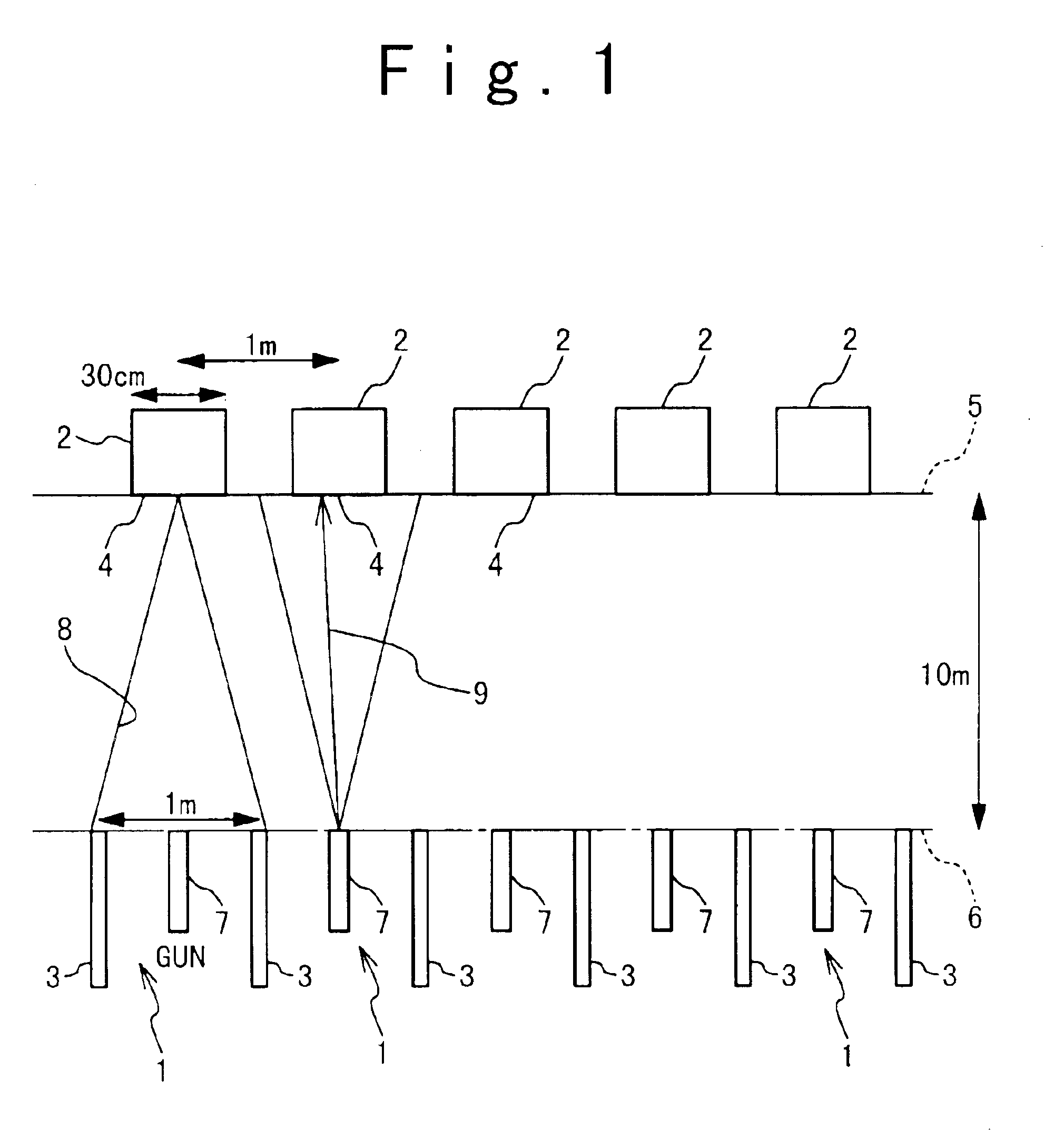
[0048]FIG. 1 shows a layout of a plurality of shooting boxes and a plurality of shot position detectors 2 in the shooting system using the laser guns according to the first embodiment of the present invention. In FIG. 1, one gun corresponds to one target. Referring to FIG. 1, the number of shooting boxes 1 is exemplified as five, and the number of shot position detectors 2 is also exemplified as five. That is, the shot position detector 2 is provided for each of the plurality of shooting boxes 1. In this example, there is no case that laser beam bullets are emitted from one shooting box 1 to the plurality of shot position detectors 2. Even if there is such a case, the laser beam bullet is not detected or is invalidated, as will be described later.

[0049]Each of the shooting boxes 1 is partitioned by two partitions 3. A ...


PUM


Abstract

In a laser gun, a signal generating unit generates an emission permission signal in response to a shooting permission signal. A laser beam bullet emitting unit emits a laser beam bullet based on the emission permission signal generated by the signal generating unit in response to an operation of the trigger.

Description

BACKGROUND OF THE INVENTION[0001]1. Field of the Invention[0002]The present invention relates to a laser gun, a target box, a shooting box and a laser gun shooting system.[0003]2. Description of the Related Art[0004]Shooting competitive sports are known. In such shooting competitive sports, it has been desired that a laser gun should substitute a gun for shooting with live bullets which need much care in view of safety and handling. There are various types of laser guns, e.g., a laser gun using flash light which has been developed for the shooting sport, and a laser gun used for exercises and connected with a computer with a cable to display the bullet arrival.[0005]It has been demanded that the laser gun should be connected with no cable. Also, it has been demanded to establish a more strict one-to-one relationship between a laser gun and a target. Hence, it has been desired to supply an optical system in which the precision in detecting a position shot by a laser beam is improved....

Claims


Application Information

Patent Timeline
IPC IPC(8): F41A33/00F41A33/02F41J5/00F41J5/02F41G3/26F41G3/00A63H33/18
CPCF41A33/02F41G3/2655F41G3/2666F41J5/02F41A33/00
Inventor HASEBE, HIROYUKIOKI, MAKOTO
Owner NEC CORP
Why Eureka
Try Eureka