Recirculation unit for a fuel cell system

A fuel cell system and fuel cell technology, which is applied to fuel cells, fuel cell additives, circuits, etc., can solve the problems of loss, the loss of hydrogen gas is higher than the necessary loss, and achieve the effect of low-cost implementation and implementation

Inactive Publication Date: 2014-02-05
DAIMLER AG
View PDF7 Cites 7 Cited by
  • Summary
  • Abstract
  • Description
  • Claims
  • Application Information

AI Technical Summary

Problems solved by technology

[0011] This method also has the decisive disadvantage that the hydrogen loss here is significantly higher than necessary, since the hydrogen must first overcome the length of the line between the discharge valve and the cathode area before it can be detected
Hydrogen in this pipeline length must be lost uselessly in each exhaust process

Method used


Image

  • Recirculation unit for a fuel cell system

Examples


Embodiment Construction

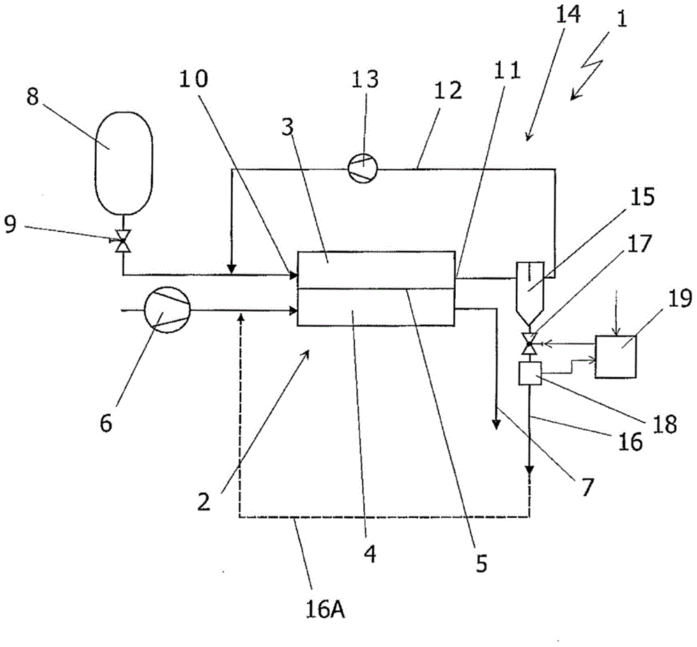
[0025]The diagrams in the figures illustrate the principle of the fuel cell system 1 . The core of the fuel cell system 1 is the fuel cell 2, which is designed as a stack of several individual fuel cells, a so-called fuel cell stack. The fuel cell 2 has an anode region 3 and a cathode region 4 which are separated by a proton-conducting membrane 5 . Thus, the fuel cell 2 is a PEM fuel cell. The filtered air is fed as an oxygen-containing medium to the cathode region 4 of the fuel cell 2 via the air feed device 6 . The used exhaust gas is discharged from the fuel cell system 1 through the exhaust gas duct 7 . The above-mentioned exhaust gases can, for example, be released into the environment, relieved of pressure (entspannt) by means of a turbine and / or supplied to combustion. But this is irrelevant for the invention.

[0026] The hydrogen in the compressed gas store 8 is fed to the anode region 3 of the fuel cell 2 via a valve and a pressure regulator 9 . The fresh hydrog...


PUM


Abstract

The invention relates to a recirculation unit (14) for a fuel cell system (I) comprising at least one fuel cell (2) which has an anode region (3) and a cathode region (4), comprising a recirculation line (12) which connects the outlet (11) of the anode region (3) to the inlet (10) thereof, comprising a liquid separator (15), which is arranged in the area of the recirculation line (12), and which comprises a discharge line (16) having a discharge valve (17) for liquid and / or gases. The invention is characterized in that a bubble sensor (18) for controlling the discharge valve (17) is arranged in the area of the discharge line (16). A method for discharging liquid and / or gases from such a recirculation unit (14) provides for the discharge valve (17) to be opened and then closed as a function of an event detected by the bubble sensor (18).

Description

technical field [0001] The invention relates to a recirculation device for a fuel cell system according to the type defined in detail in the preamble of claim 1 . Background technique [0002] Known from the general prior art is a fuel cell system which is operated with gaseous reactants, for example air and hydrogen or a gas containing hydrogen. They generally have at least one fuel cell with an anode region and a cathode region. Typically, the fuel cells described above are stacked from a plurality of individual fuel cells and are called a fuel cell stack. In such fuel cells, especially those with PEM technology, the exhaust gas from the anode area is usually collected together and re-sent into the anode area together with fresh gas - especially fresh hydrogen . For this purpose a recirculation device is required. [0003] Such a recirculation device is described under the title "fuel circuit" in the related WO 2008 / 052578 A1. In this recirculation device, the exhaust...

Claims


Application Information

Patent Timeline
Patent Type & Authority Applications(China)
IPC IPC(8): H01M8/04B01D5/00
CPCH01M8/04843H01M8/04164H01M8/04097Y02E60/50B01D19/0063
Inventor A·穆特施尔
Owner DAIMLER AG
Why Eureka
Try Eureka