Disc device

a disc device and disc technology, applied in the field of disc devices, can solve the problems of increasing operating noise, affecting the recording quality of the disc, so as to achieve the effect of reducing the operating nois

Inactive Publication Date: 2005-11-08
ALPINE ELECTRONICS INC
View PDF5 Cites 12 Cited by
  • Summary
  • Abstract
  • Description
  • Claims
  • Application Information

AI Technical Summary

Benefits of technology

[0010]In order to solve the problems in the related art, it is an object of the presently preferred embodiments to provide a disc device that the user can load the disc smoothly without having abnormal feeling in his / her hand when inserting the disc through the insertion slot, and in which the operation noise may be reduced.
[0012]In this disc device, as the transfer unit is switched into a high-speed operation when the disc reaches the transfer unit that is already operated at a low-speed, or after a predetermined period of time (for example, hundreds ms) has elapsed from then on, the disc is retracted into the device smoothly without giving such abnormal feeling that the disc abuts against the transfer unit or a feeling that the disc is violently retracted into the device to the user when he / she inserted the disc by hand.
[0014]In this case, since the transfer unit operates at a low-speed from the moment when the transfer unit is actuated until the disc is inserted, noise due to the idling of the transfer unit until the disc is inserted may be reduced.
[0016]In such a case, as the transfer unit is actuated at a low-speed upon insertion of the disc, and subsequently, is switched into high-speed operation when the disc reaches the transfer unit or after a predetermined period of time is elapsed from then on, idling operation of the transfer unit before insertion of the disc is not necessary, and thus the operating noise is reduced.

Problems solved by technology

However, these conventional methods have problems.
This tends to leave an abnormal feeling to the user's hand when inserting the disc.
Consequently, operating noise increases.
Thus, the user feels that the disc is violently retracted into the device by the transfer unit when the user inserted the disc into the insertion slot by hand.

Method used


Image

  • Disc device
  • Disc device
  • Disc device

Examples


Embodiment Construction

[0010]In order to solve the problems in the related art, it is an object of the presently preferred embodiments to provide a disc device that the user can load the disc smoothly without having abnormal feeling in his / her hand when inserting the disc through the insertion slot, and in which the operation noise may be reduced.

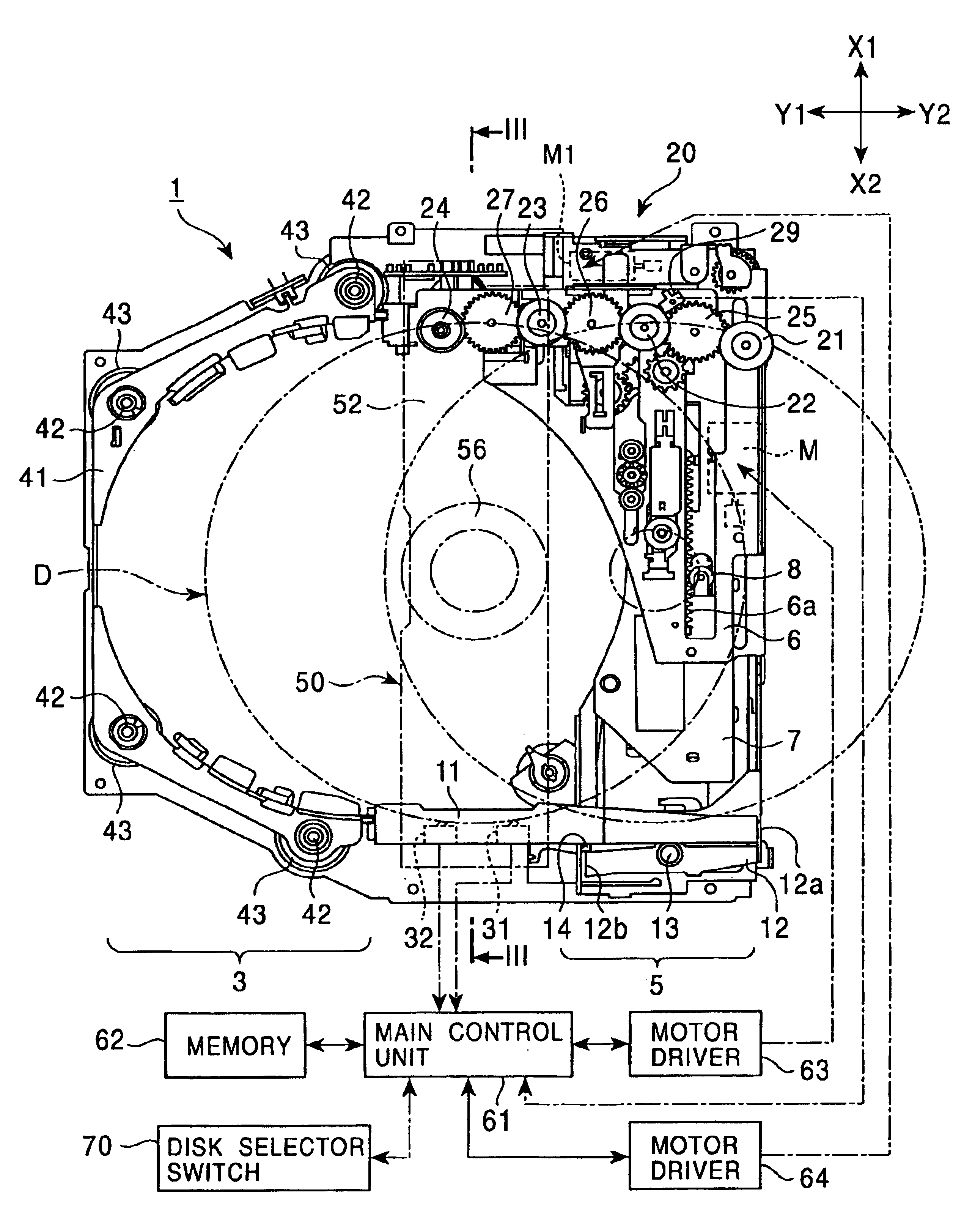
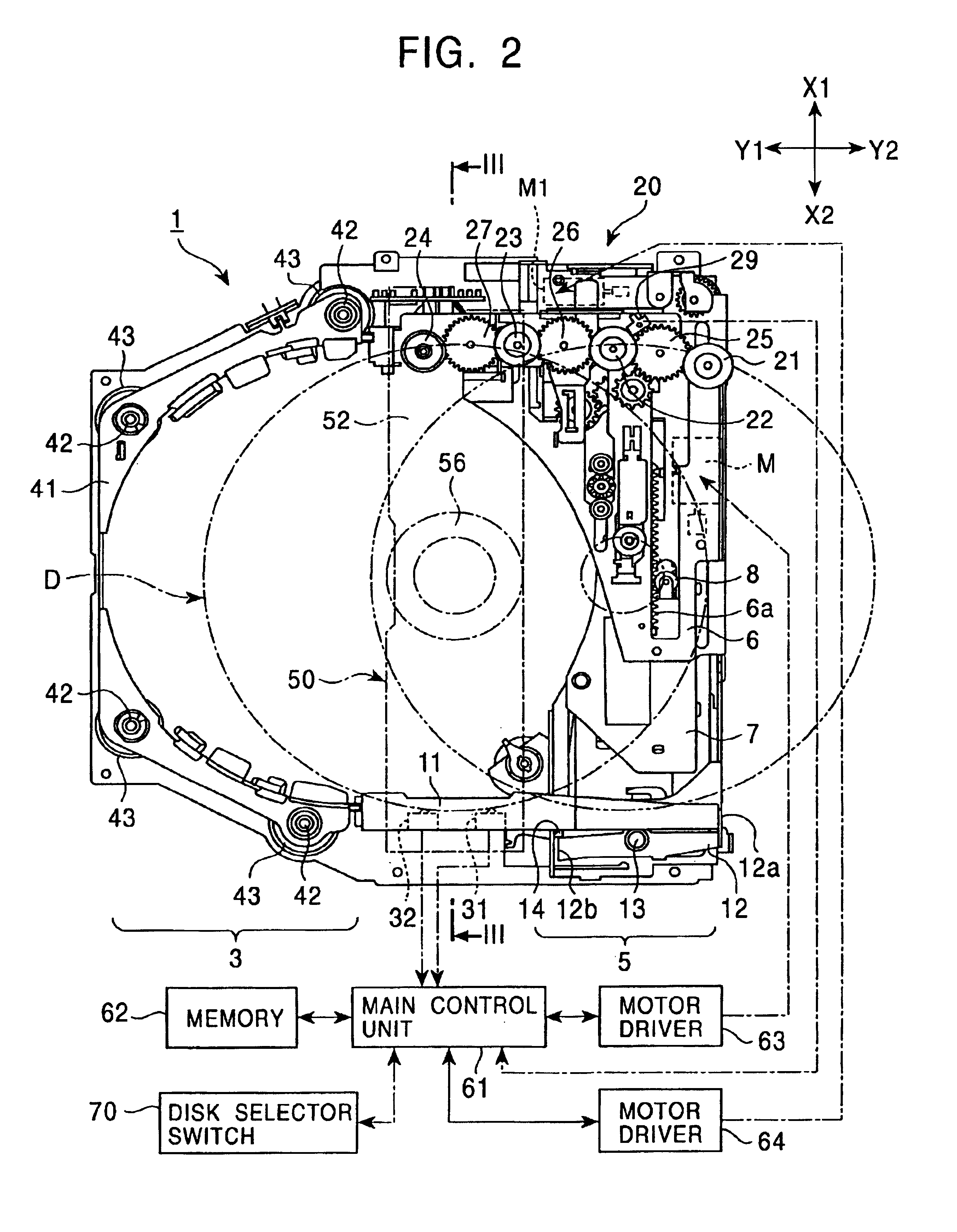
[0011]In an embodiment, a disc device includes a transfer unit for giving a transferring force to a disc inserted from the outside to transfer the same in the storage area in the device, a sensor unit for detecting the position of insertion of the disc inserted from the outside, and a control unit for controlling an operational speed of the transfer unit. The control unit controls the operational speed of the transfer unit in the disc loading direction at a low-speed until the disc inserted from the outside reaches the transfer unit, and then switches the operational speed of the transfer unit in the disc loading direction from a low-speed to a high-speed when th...


PUM

PropertyMeasurementUnit
diameteraaaaaaaaaa
diameteraaaaaaaaaa
operational speedaaaaaaaaaa

Abstract

A disc device comprising a transfer unit operable to provide a transferring force to a disc inserted from the outside to transfer the disc into a storage area in the device, a sensor unit for detecting the position of the inserted disc, and a control unit for controlling a operational speed of the transfer unit. The control unit controls the operational speed of the transfer unit in the disc loading direction at a low-speed until the disc inserted from the outside reaches the transfer unit. The control unit then adjusts the operational speed of the transfer unit in the disc loading direction from a low-speed to a high-speed when the sensor unit detects that the disc is inserted into the position in which a transferring force from the transfer unit is given to the disc, or after a predetermined period of time has elapsed. Accordingly, the disc device reduces operation noise and resistance when the disc is inserted.

Description

RELATED APPLICATIONS[0001]Pursuant to 35 U.S.C. § 119, the benefit of priority of the filing date of Nov. 6, 2001, of Japanese Patent Application Number 2001-340997, filed on the aforementioned date, the entire contents of which is incorporated herein by reference, is claimed.BACKGROUND OF THE INVENTION[0002]1. Field of the Invention[0003]The present invention relates to a disc device in which a disc such as a compact disc or a digital video disc is loaded, and more specifically, to a disc device capable of transferring the disc smoothly when it is inserted.[0004]2. Description of the Related Art[0005]An in-vehicle disc device typically includes an insertion slot formed on the front surface of the device and a transfer unit located inside the insertion slot. The transfer unit enables the disc to be inserted through the insertion slot and into the device. The transfer unit may utilize a roller for exerting a transporting force to the disc.[0006]In-vehicle disc devices may also includ...

Claims


Application Information

Patent Timeline
Patent Type & Authority Patents(United States)
IPC IPC(8): G11B17/22G11B17/04G11B17/051
CPCG11B17/0404G11B17/051G11B17/223
Inventor OTSUKI, AKIRAITO, MASATOSHI
Owner ALPINE ELECTRONICS INC
Why Eureka
Try Eureka