Subsampling communication receiver architecture with relaxed IFA readout timing
What is Al technical title?
Al technical title is built by PatSnap Al team. It summarizes the technical point description of the patent document.
a receiver and subsampling technology, applied in the field of subsampling receiver architectures, can solve the problems of poor linearity, sensitivity to clock jitter, and inability to directly extend to general modulation schemes
Inactive Publication Date: 2005-11-08
TEXAS INSTR INC
View PDF6 Cites 25 Cited by
Summary
Abstract
Description
Claims
Application Information
AI Technical Summary
This helps you quickly interpret patents by identifying the three key elements:
Problems solved by technology
Method used
Benefits of technology
Problems solved by technology
However, its application is not directly extendable to general modulation schemes.
However, this design trades one set of problems for another.
Exemplary disadvantages in such receivers typically include sensitivity to clock jitter and poor linearity.
The signal-to-noise ration of such stages are limited by th
Method used
Image
Click on the blue label to locate the original text in one second.
Reading with bidirectional positioning of images and text.
Examples
Embodiment Construction
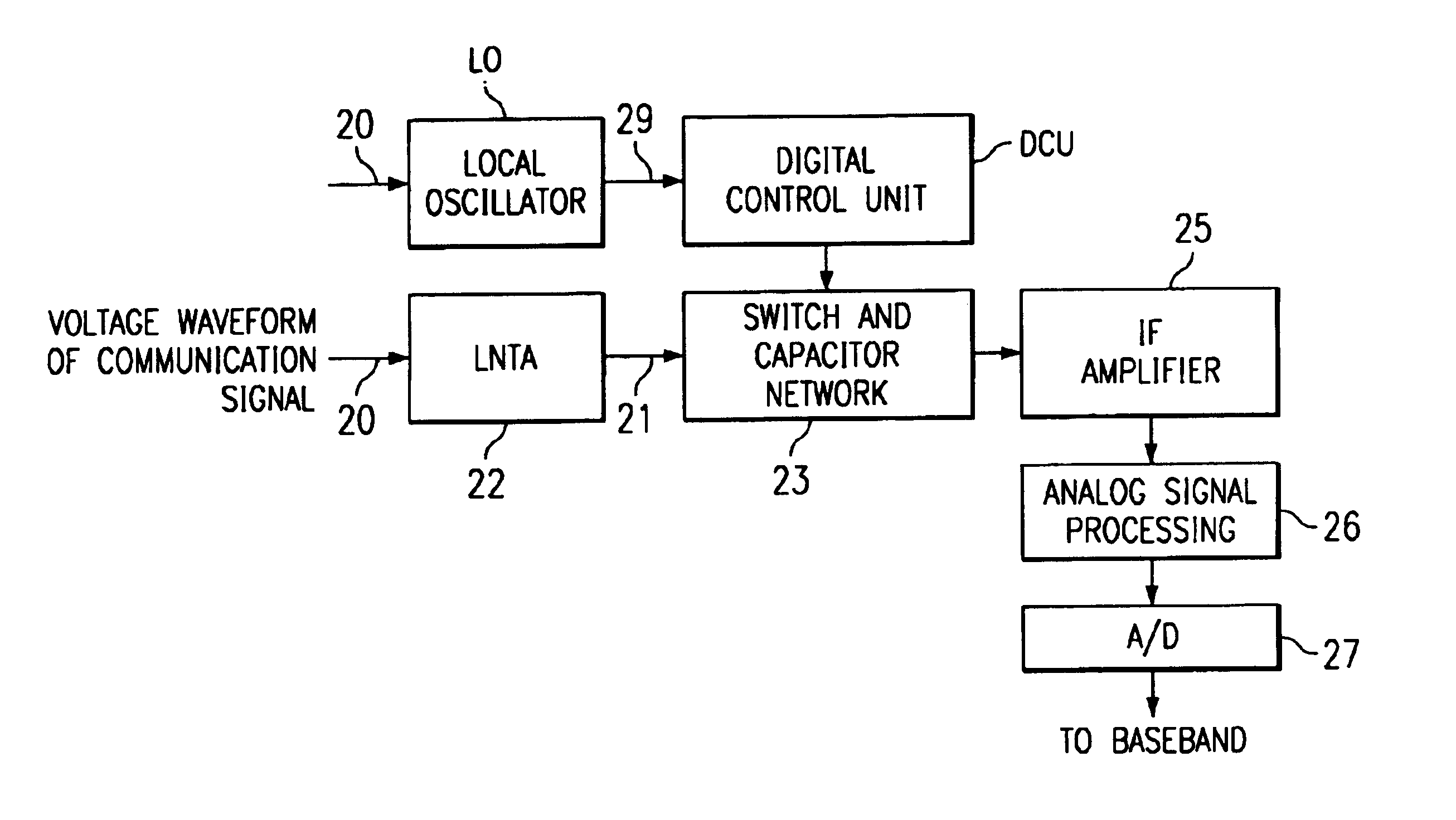
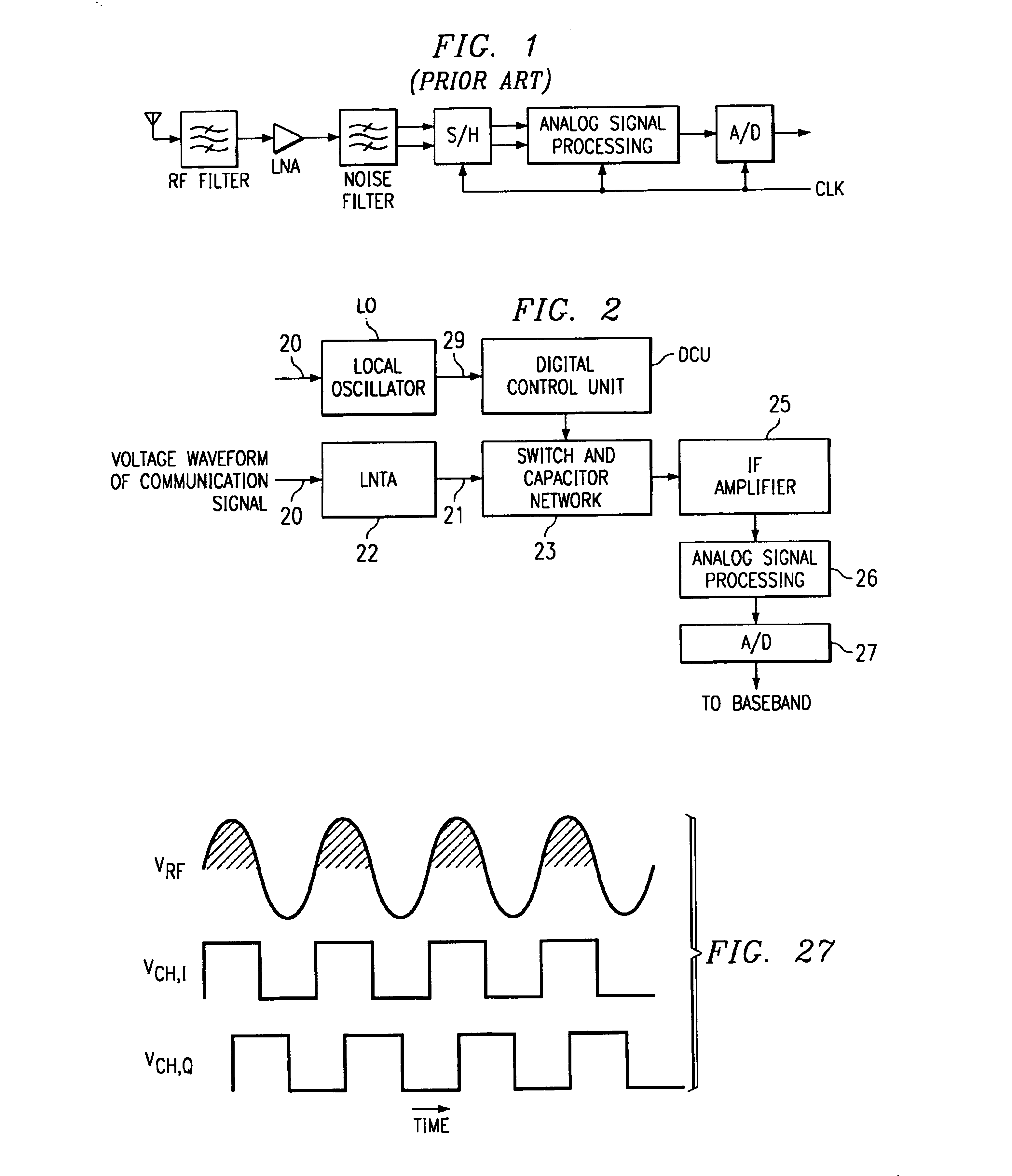
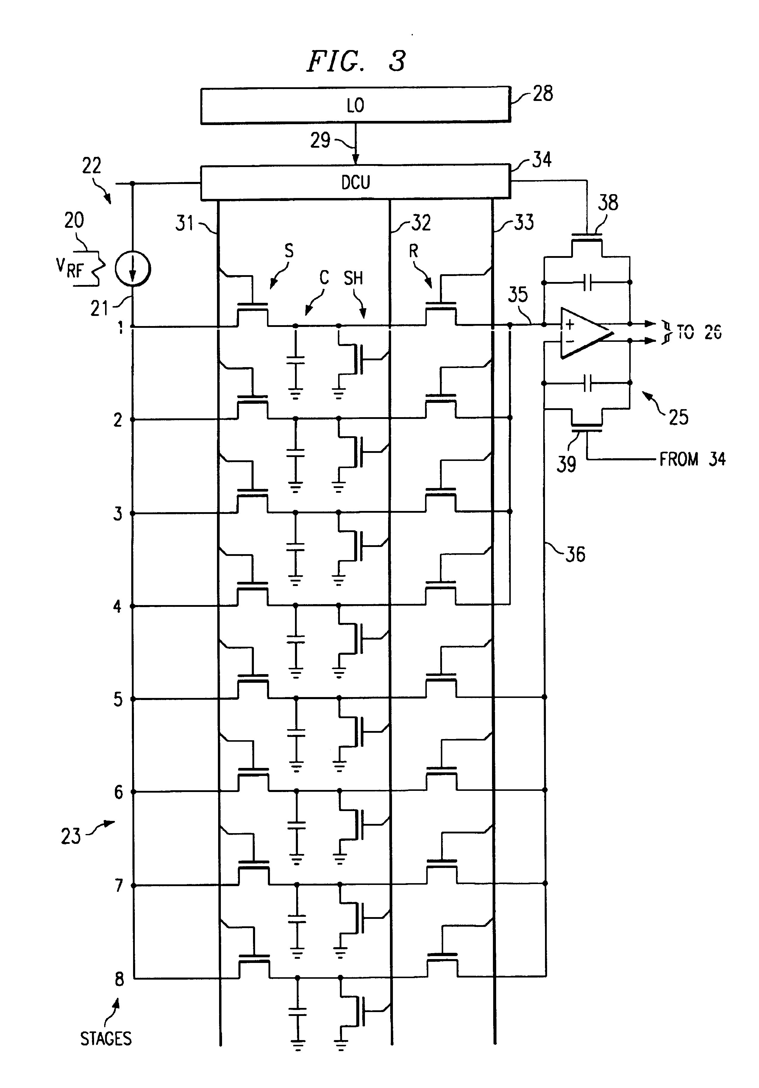
[0041]FIG. 2 diagrammatically illustrates pertinent portions of exemplary embodiments of a subsampling communication receiver according to the invention. The subsampling receiver architecture of FIG. 2 includes an input 20 for receiving the voltage waveform of a communications signal, for example an RF communication signal. This voltage waveform is applied to a low noise transconductance amplifier (LNTA) 22 which can use conventional techniques to transform the voltage waveform at 20 into a corresponding current waveform at 21. In some embodiments, the LNTA 22 can include a conventional low-noise amplifier (LNA) followed by a conventional transconductance amplifier (TA). The current waveform at 21 is applied to a switch and capacitor network 23. Switches in the network 23 are operable for sampling the current waveform, and capacitors in the network 23 are operable for integrating the current waveform samples. A digital control unit (DCU) controls the operation of the switches in the...
PUM
Abstract
A first periodic voltage waveform (20) is downconverted into a second periodic voltage waveform (35, 36). A plurality of temporally distinct samples (SA1, SA2, . . . ) respectively indicative of areas under corresponding fractional-cycles of the first voltage waveform are obtained. The samples are combined to produce the second voltage waveform, and are also manipulated to implement a filtering operation such that the second voltage waveform represents a downconverted, filtered version of the first voltage waveform. The second waveform is driven by an amplifier stage (25), and the second waveform can be advantageously constructed so as to permit the amplifier stage to perform internal resets, offset corrections and other ancillary amplifier stage adjustments without losing information in the first waveform.
Description
[0001]The present application is a continuation-in-part of copending U.S. Ser. No. 10 / 099,831 filed on Mar. 15, 2002, and the present application claims the priority under 35 USC 119(e)(1) of the following U.S. provisional applications: 60 / 286,421, 60 / 286,564, 60 / 286,736, 60 / 286,787, and 60 / 286,788, all filed on Apr. 25, 2001; and 60 / 343,653, 60 / 344,262, 60 / 343,938 all filed on Dec. 29, 2001 and 60 / 343,673, all filed on Dec. 28, 2001. The present application discloses subject matter that is related to subject matter disclosed in copending U.S. Ser. No's. 10 / 132,624 and 10 / 132,025, both filed concurrently herewith. All of the aforementioned applications are incorporated herein by reference.FIELD OF THE INVENTION[0002]The invention relates generally to communication receivers and, more particularly, to subsampling receiver architectures.BACKGROUND OF THE INVENTION[0003]A recent trend in direct-conversion receivers is to use subsampling. The basic approach is to sample the RF signal at...
Claims
Application Information
Patent Timeline
Application Date:The date an application was filed.
Publication Date:The date a patent or application was officially published.
First Publication Date:The earliest publication date of a patent with the same application number.
Issue Date:Publication date of the patent grant document.
PCT Entry Date:The Entry date of PCT National Phase.
Estimated Expiry Date:The statutory expiry date of a patent right according to the Patent Law, and it is the longest term of protection that the patent right can achieve without the termination of the patent right due to other reasons(Term extension factor has been taken into account ).
Invalid Date:Actual expiry date is based on effective date or publication date of legal transaction data of invalid patent.