Dual lock apparatus

a technology of double locks and locks, applied in the field of double locks, can solve the problems of door swinging freely, slave key holders, disassembly and fixing,

Inactive Publication Date: 2005-11-15
INOVEC
View PDF16 Cites 24 Cited by
  • Summary
  • Abstract
  • Description
  • Claims
  • Application Information

AI Technical Summary

Benefits of technology

[0019]This provides a significant advantage where the use of a master key in conjunction with a slave key enables one that has a master key to control whether others that have slave keys can in fact operate a particular lock.
[0020]In addition, the above provides the advantage that if the secondary locking mechanism is one that may be exposed to potential failure, the primary locking means ensures that there is a safeguard in that the lock can always be operated even if the secondary locking means has ceased to function.
[0023]It is preferred that said second activation unit includes an electric motor that engages said slider by a rack having a slit and a recess, the mechanical coupling of the slider with the rack achieved by a plunger fixedly attached to said slider and having a projection correspondingly dimensioned to said recess, said plunger movable between a first and a second position, in a said first position said projection engaging with said recess to thereby effectively mechanically couple said second activation unit to said slider and thus the bolt and in said second position said projection enters the slit within which it may slidably move to thereby effectively decouple said second activation unit to the slider.

Problems solved by technology

There have also been developed locks that are not only operable by the use of the slave key but also a master key, allowing the master key holder, for example, to operate all doors in a pre-defined area whilst the slave key holders are limited to being able to operate specific doors only.
The difficulty with these type of arrangements is that if the electric motor was for whatever reason inoperable, the door may be left either in the unlocked or locked state and may require disassembly to be fixed.
Further still, the difficulty with some existing locks is that although the door may be unlocked, that is it may be opened, the bolt still engages a portion of the door frame and further manual operation of the bolt by the use of a handle is required to be able to open the door.
On the other hand, if the bolt was to be retracted fully, then the door may swing freely, also an undesirable effect.

Method used


Image

  • Dual lock apparatus
  • Dual lock apparatus
  • Dual lock apparatus

Examples


Embodiment Construction

[0036]The following detailed description of the invention refers to the accompanying drawings. Although the description includes exemplary embodiments, other embodiments are possible, and changes may be made to the embodiments described without departing from the spirit and scope of the invention. Wherever possible, the same reference numbers will be used throughout the drawings and the following description to refer to the same and like parts.

[0037]The present invention relates to locks and in particular to locks that are used for hollow winged aluminium doors and the like. It may also be adapted to be used on other type of doors such as sliding doors. It is not intended to limit the invention to any particular type of lock or door.

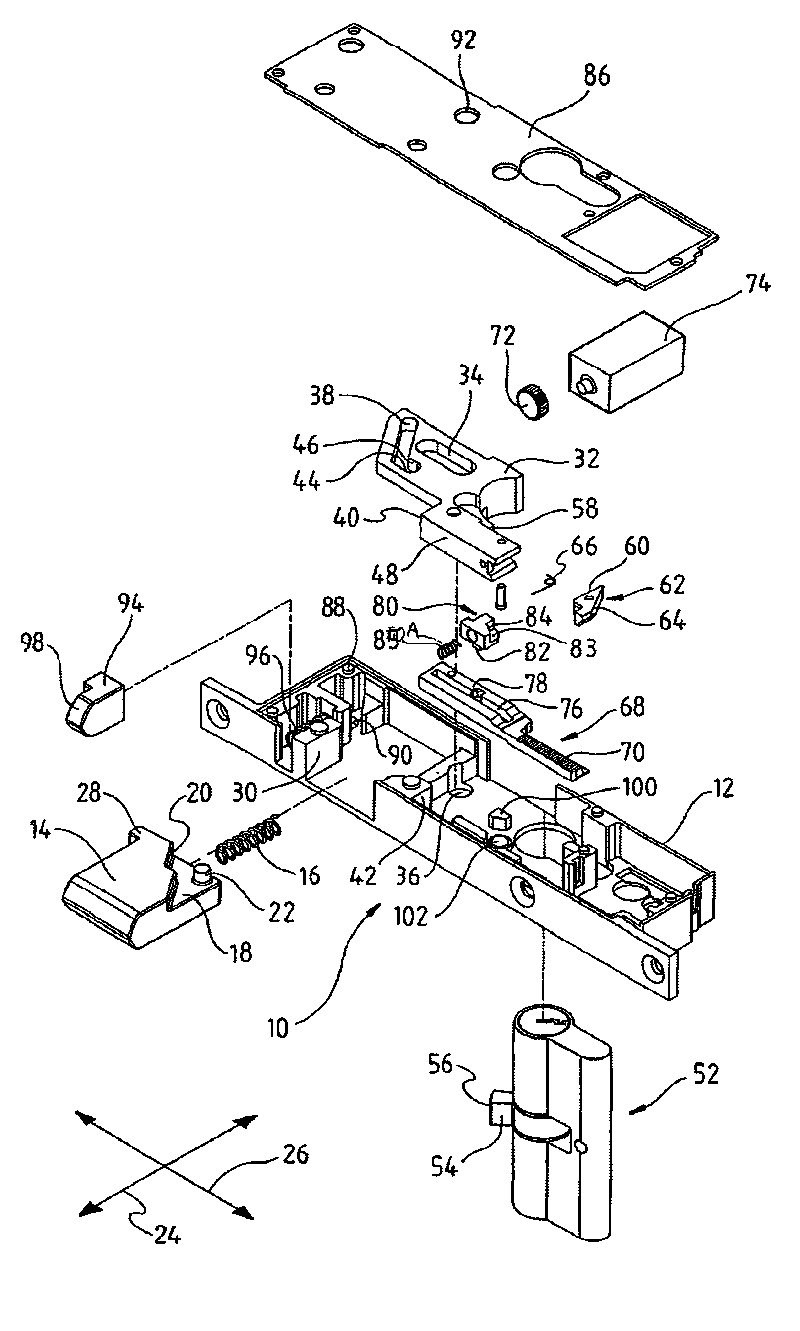
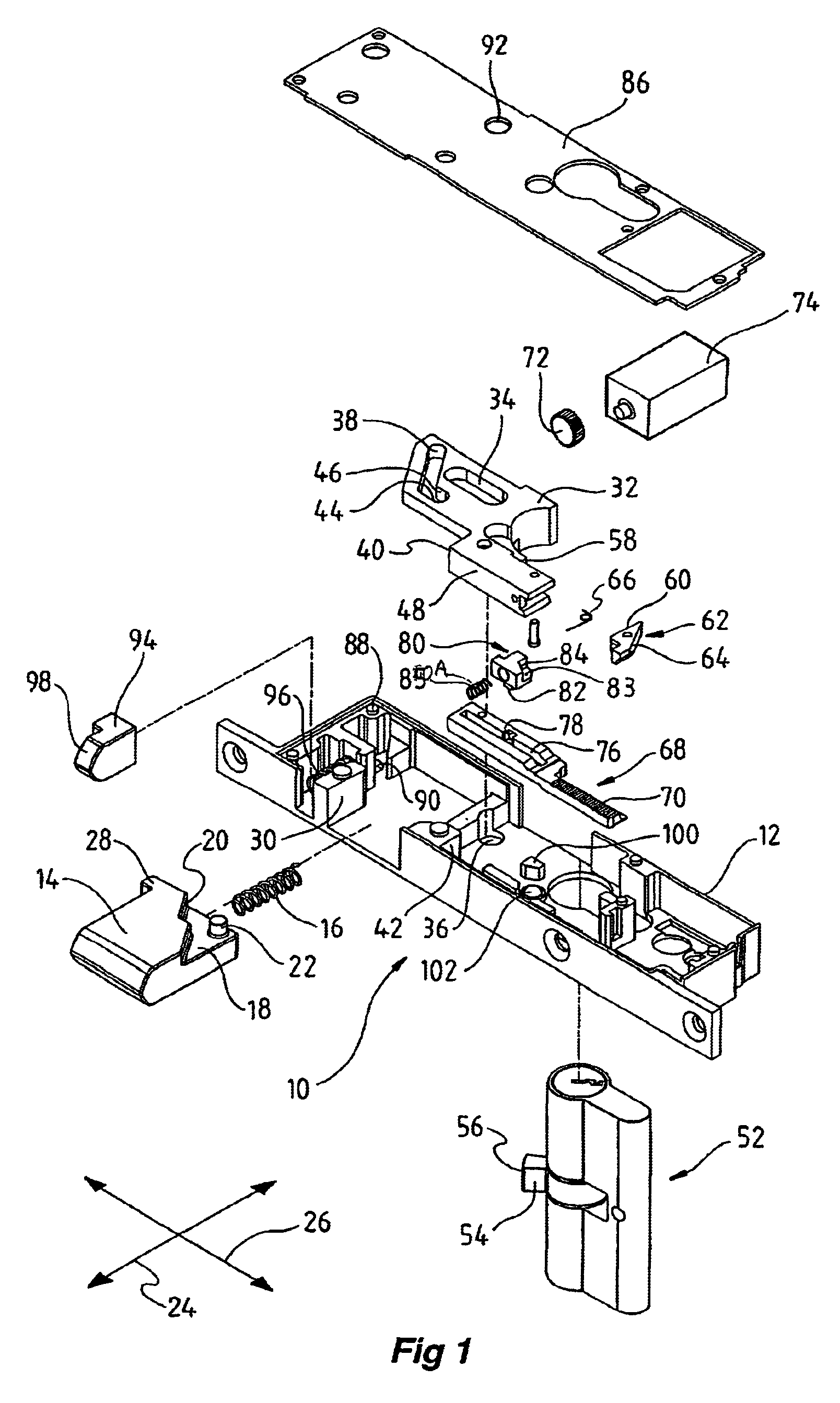
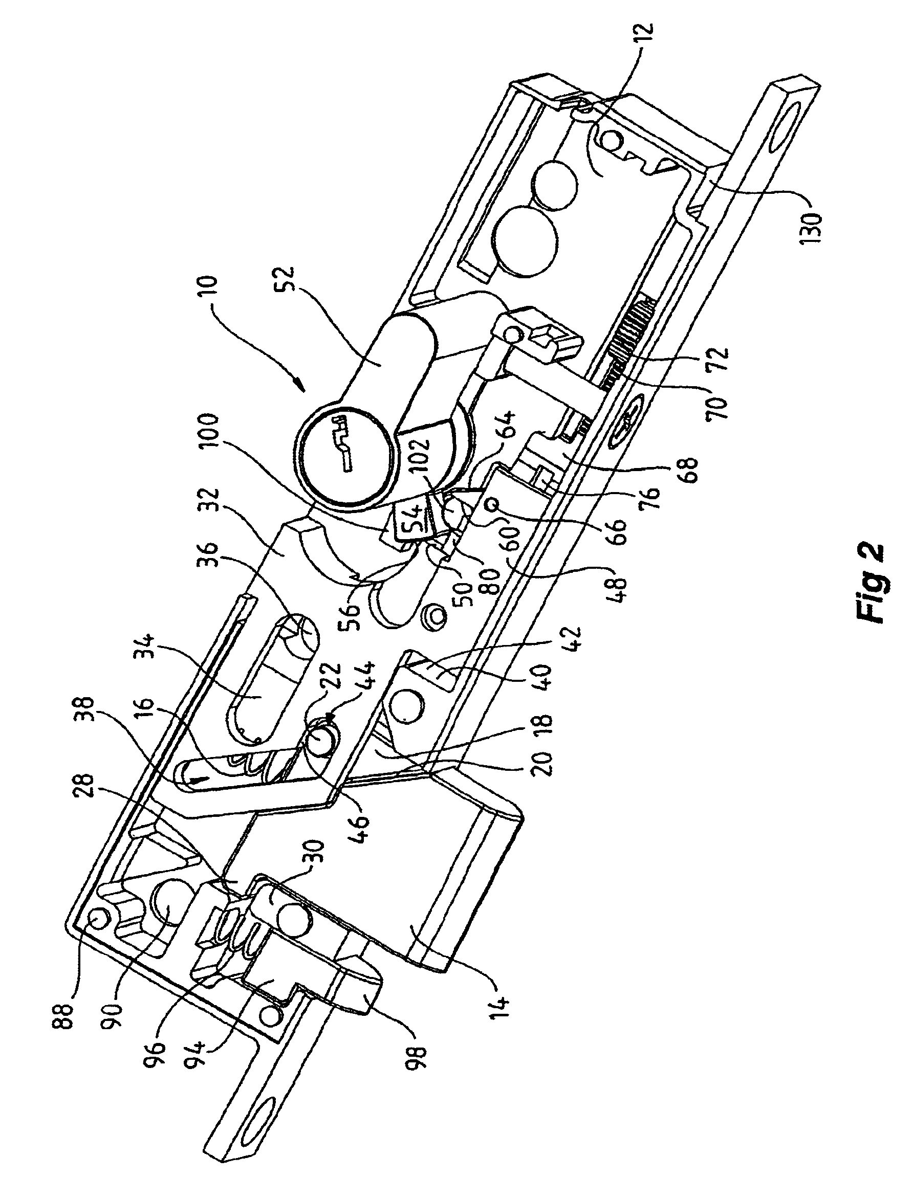
[0038]Shown in FIGS. 1 and 2 is a lock 10 according to a first embodiment of the present invention. A casing 12 is adapted to slidingly support a locking bolt 14 said bolt being biased outwardly from said casing by the use of spring 16. The bolt 14 inclu...


PUM


Abstract

The present invention relates to a lock arrangement having a lock (14) and including a first locking device (52) adapted to operate the lock to lock and unlock the lock. A second locking device (68) includes a member (32) moveable between a first and a second position wherein when the member (32) is in the first position the lock is locked and when in the second position the lock is unlocked. Generally the first locking device (52) is key operated and the second locking device (68) is driven by an electric motor (72). The first locking device (52) can operate the lock independently of the member (32) and regardless of its position and when used to lock or unlock the lock can decouple through a clutch mechanism (80) the second locking device (68) from controlling the lock.

Description

[0001]The present invention relates to a dual lock apparatus and in particular to a dual lock apparatus that has at least two independent means of acting on a lock.BACKGROUND OF THE INVENTION[0002]There are numerous types of locks in existence today that are used to secure various devices. One of the more common uses of locks is in relation to doors. Typically door locks have a bolt that can be extended from a locking mechanism so as to engage a doorframe or furniture with the bolts being driven by the use of a unique or slave key. There have also been developed locks that are not only operable by the use of the slave key but also a master key, allowing the master key holder, for example, to operate all doors in a pre-defined area whilst the slave key holders are limited to being able to operate specific doors only. This however requires the master key and the slave key to be of the same type thus potentially comprising security.[0003]There have also been developed electromechanical...

Claims


Application Information

Patent Timeline
Patent Type & Authority Patents(United States)
IPC IPC(8): E05B63/00E05B35/10E05B35/00E05B47/00
CPCE05B35/10E05B63/0017E05B47/0012E05B2047/0016E05B2047/002E05B2047/0026E05B2047/0086Y10T70/7107Y10T70/7073Y10T70/7113E05B2047/0093
Inventor KEIGHTLEY, KYM JOHN
Owner INOVEC
Why Eureka
Try Eureka