Switching amplifier for driving reactive loads

a technology of reactive load and switching amplifier, which is applied in the direction of amplifiers with semiconductor devices/discharge tubes, generators/motors, negative-feedback circuit arrangements, etc., can solve the problems of requiring 40 rails, low power dissipation, and large physical space occupied by storage capacitors, so as to reduce the energy storage requirements of power supplies and reduce the effect of ripple-current smoothing ability

Inactive Publication Date: 2011-04-26
SUMMIT APPLIED RES INC
View PDF20 Cites 22 Cited by
  • Summary
  • Abstract
  • Description
  • Claims
  • Application Information

AI Technical Summary

Benefits of technology

[0017]In a switching amplifier embodying a first aspect of the invention, a substantial portion of the baseband current is isolated from the power supply—illustratively by being kept internal to the load. As a result, the currents, especially time-varying currents, that flow through the power supply are much lower than they otherwise would be. This, in turn, results in much more relaxed ripple-current-smoothing capabilities and lower energy storage requirements for the power supply. The power supply's storage elements can thus be made much smaller than in the prior art, thereby achieving a smaller physical volume for the power supply overall and thus significantly overcoming the drawbacks of prior art switching amplifiers relating to the large physical volume of the power supply storage elements. (Certain embodiments may utilize multiple power supplies. The term “power supply” as used herein is intended to encompass such arrangements.)

Problems solved by technology

Rather, energy flowing out of the load is converted to heat, resulting in inefficiency.
The others are railed and consequently have low power dissipation.
Thus, disadvantageously, a relatively large amount of physical space is taken up by the storage capacitors.
Among the disadvantages of the multi-rail approach is that in order to achieve comparable efficiencies to switching amplifiers, 20 to 40 rails are required.
For that same reason, however, use of a multi-rail amplifier may be disadvantageous, or completely impractical, in applications having stringent volume requirements, such as submarine-based sonar systems, or where cost is a major concern.
Although the switching amplifier solution does not involve the high component counts characteristic of multi-rail amplifiers, it also has its drawbacks.
In particular, the variation in current flow through the power supply resulting from the flow of baseband current to and from the load can cause variations in power supply voltage, giving rise to load signal distortion.
Indeed, the storage capacitors often dominate the volume of the power supply.
As with the multi-rail approach, this is a disadvantage in applications in installations where physical space is at a premium.
A further drawback of the switching amplifier approach arises when the switching amplifier is used to drive capacitive loads.
Such currents will otherwise cause dissipative loss, damage the load and impair the function of the semiconductor switches.
However, the impedance of a capacitive load, such as a piezoelectric transducer, decreases with frequency.
A more complex and physically larger load filter is thus required for capacitive loads.
This constraint is, again, a problem in applications where physical space is at a premium.

Method used


Image

  • Switching amplifier for driving reactive loads
  • Switching amplifier for driving reactive loads
  • Switching amplifier for driving reactive loads

Examples


Embodiment Construction

les of the invention using complementary N channel FETs and P channel FETs;

[0032]FIG. 4B is a circuit diagram of a switching amplifier similar to that shown in FIG. 4A but using only N channel FETs;

[0033]FIGS. 5A and 5B show the magnitude of the Fourier coefficients of various switching signal waveforms, useful in explaining the principles of the present invention;

[0034]FIG. 6A is an example of a balanced piezoelectric stack actuator that can be driven by a switching amplifier embodying the principles of the present invention, the stacks being mechanically in parallel;

[0035]FIG. 6B is an example of a balanced piezoelectric stack actuator that can be driven by a switching amplifier embodying the principles of the present invention, the stacks being mechanically in series;

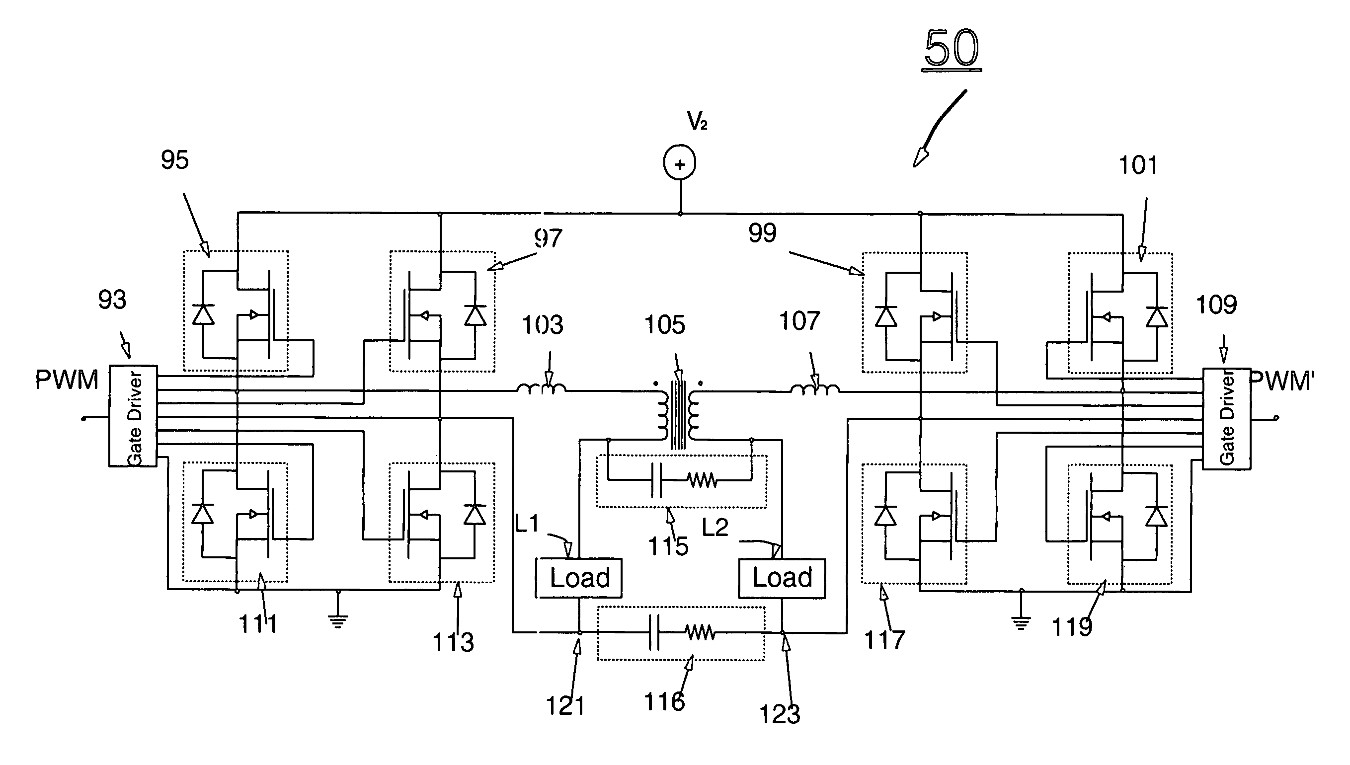
[0036]FIG. 7 is a balanced dual H-bridge switching amplifier embodying the principles of the invention;

[0037]FIG. 8 is a three-phase balanced amplifier embodying the principles of the invention using half-bridge swit...


PUM


Abstract

A switching amplifier drives balanced piezoelectric or other capacitive or reactive loads with a minimum physical electronics volume, enabling a compact arrangement that can combine amplifier and transducer at the same physical location. Power supply current is minimized by using two or more transducers driven with phase-shifted signals, resulting in stored energy being cycled between the transducers rather than being carried over the power supply lines for storage in a power supply. Auxiliary power supply capacitors to store energy coming out of the load can thus be minimized. The modulation scheme puts the switching frequencies in common-mode while the baseband signals are differential mode. The common-mode switching frequency signals are blocked from the loads by a common-mode inductor. The common-mode inductor can be physically small as a result of the large baseband load currents being in differential mode. Low-volume load filters are made possible by the fact that they are not called upon to filter signals at the fundamental switching frequency but only at higher frequencies. The loads are biased independently of the baseband signals. The switching amplifier can drive balanced loads comprising two, three or more individual load elements.

Description

CROSS-REFERENCE TO RELATED APPLICATION[0001]This application claims the benefit of U.S. provisional patent application No. 60 / 457,050 filed Mar. 24, 2003, incorporated herein by reference.FEDERALLY SPONSORED RESEARCH[0002]This work was supported under Office of Naval Research contract N00014-01-C-0063. The government has certain rights in this invention.BACKGROUND OF THE INVENTION[0003]The present invention relates to amplifiers for driving reactive loads, such as piezoelectric transducers.[0004]Piezoelectric transducers transform electrical energy into mechanical energy and vice versa. Piezoelectric material stores electrical energy that is not converted into mechanical energy. This stored electrical energy is typically larger than the converted energy. The impedance of a piezoelectric transducer is predominantly capacitive, so that the energy is stored as charge on the capacitor. When a time-varying signal is applied from an amplifier, the capacitive load charges when the voltage ...

Claims


Application Information

Patent Timeline
Patent Type & Authority Patents(United States)
IPC IPC(8): H03F3/38
CPCH03F3/2173H02N2/065
Inventor ZIPFEL, JR., GEORGE GUSTAVEZIPFEL, CHRISTIE LEWIS
Owner SUMMIT APPLIED RES INC
Why Eureka
Try Eureka