Hand-held power tool with a decoupling device

Active Publication Date: 2008-02-28
HILTI AG
View PDF15 Cites 24 Cited by
  • Summary
  • Abstract
  • Description
  • Claims
  • Application Information

AI Technical Summary

Benefits of technology

[0019] Advantageously, the second spring-mounted support has a second bar-shaped support member radially surrounded by a second tubular support member with interposition of a second elastomeric arrangement therebetween, with the second elastomeric arrangement having a region with a star-shaped cross-section. Such an elastomeric arrangement permits to set particularly good a predetermined spring stiffness that acts uniformly in the radial direction about the second bar-shaped member. In addition, this permits to produce a relatively small spring action in the rotational direction about the second bar-shaped support member. Altogether, thereby, a particularly good decoupling of the handle from the housing vibrations, which are caused by the rotational oscillations of the housing, is achieved.
[0020] It is particularly advantageous when the second elastomeric arrangement has, between the second bar-shaped support membe

Problems solved by technology

However, the drawback of the known hand-held tool consists in that despite the all-side spring action applied to both spri

Method used


Image

  • Hand-held power tool with a decoupling device
  • Hand-held power tool with a decoupling device
  • Hand-held power tool with a decoupling device

Examples


Embodiment Construction

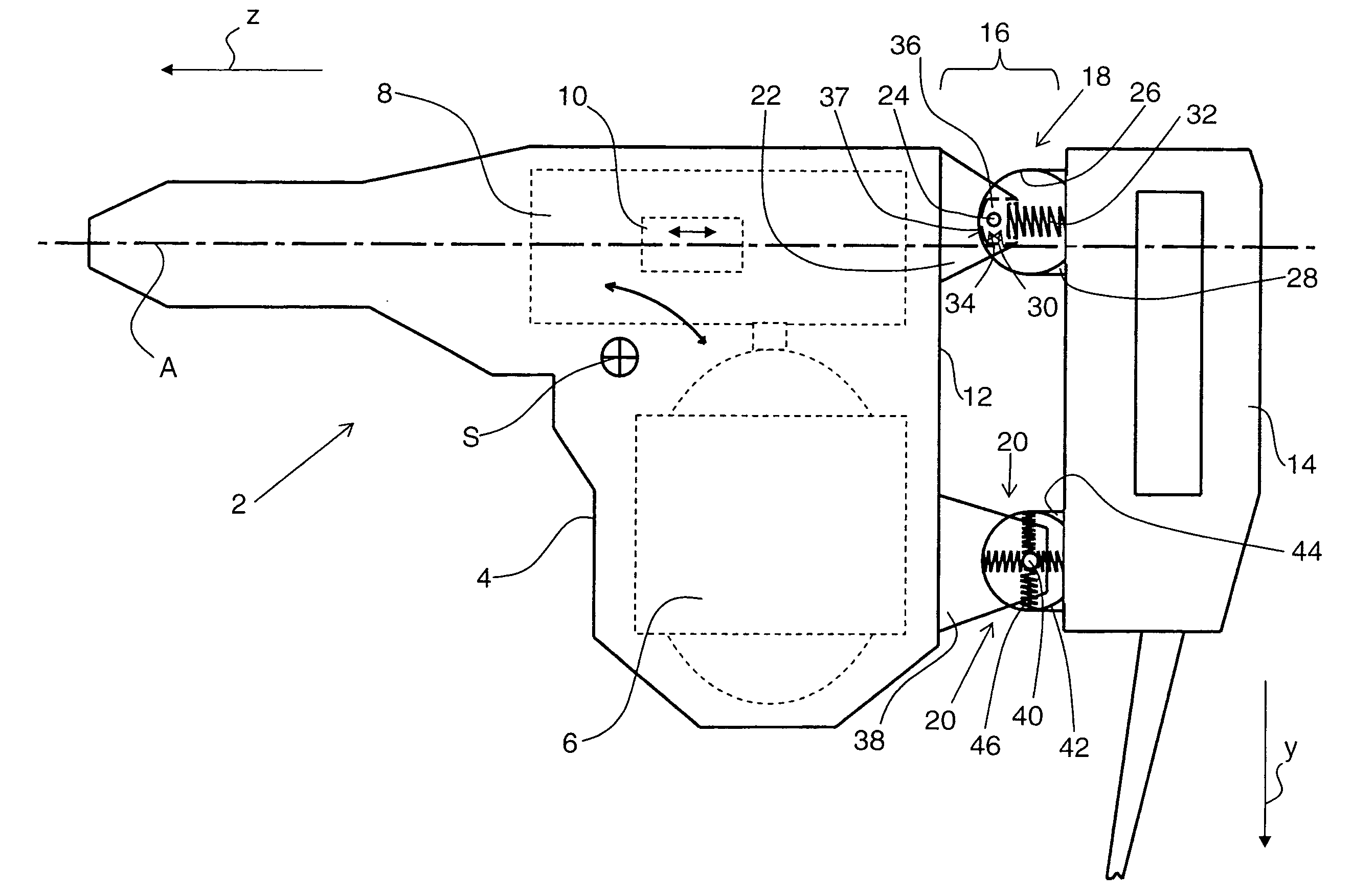
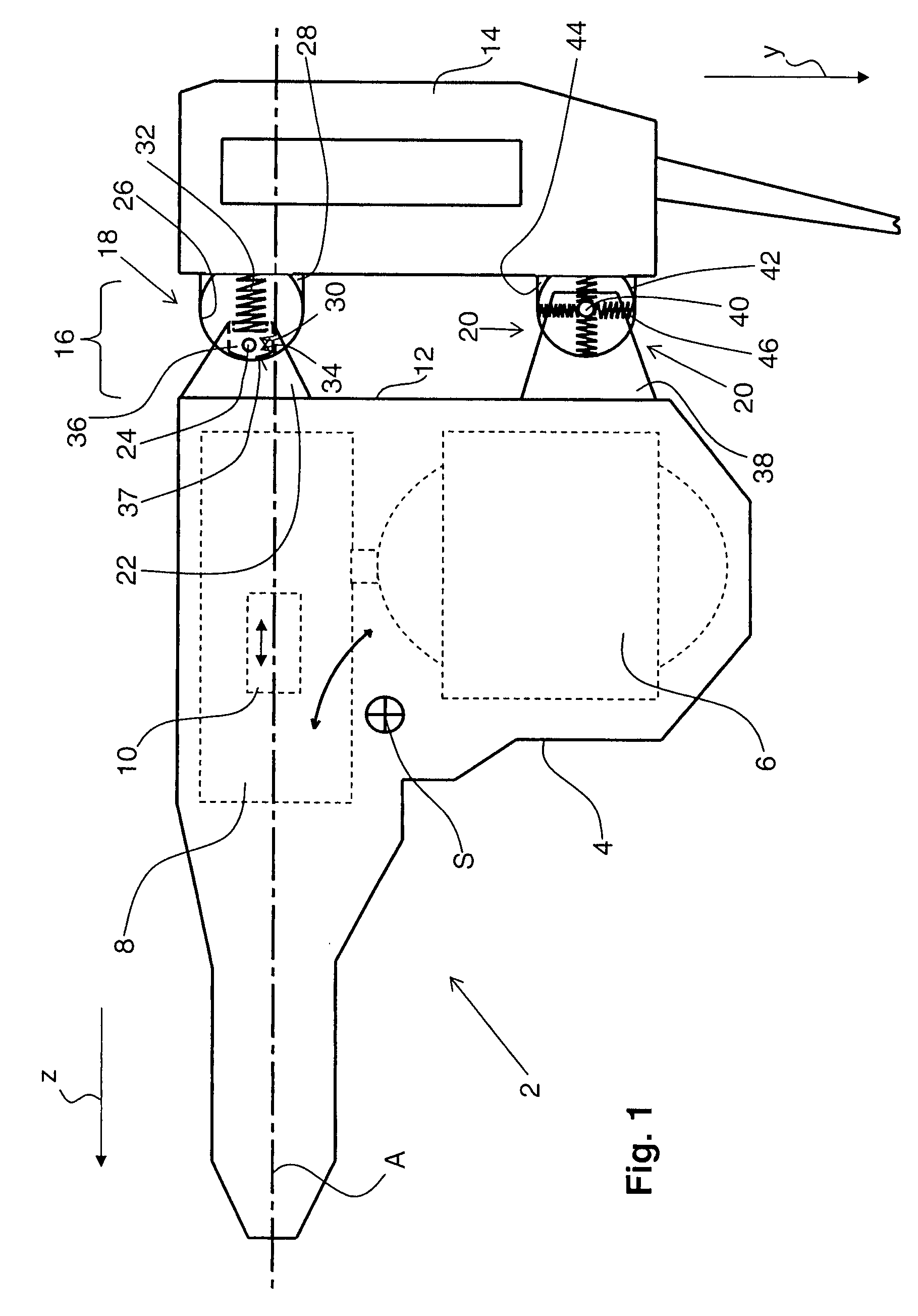
[0031]FIG. 1 shows a principal schematic view of a hand-held power tool 2 according to the present invention and which is formed as an electrical combination hammer that can be alternatively used as a hammer drill or chisel hammer. The power tool 2 has a housing 4 in which a drive motor 6 and an electro-pneumatic drive unit 8, e.g., a percussion mechanism which is driven by the electric motor 6, are located. The drive unit 8 includes a gear unit and operating means 10, e.g., in form of a percussion or impact piston that reciprocates during an operation along an operational axis A which determines a parallel first direction z that corresponds to the operational direction of the hand-held power tool 2. The operational axis A is spaced from the gravity center S of the hand-held power tool 2 which, e.g., can be defined by the gravity center of the mass of the hand-held power tool 2 in a middle position of the operational means 10.

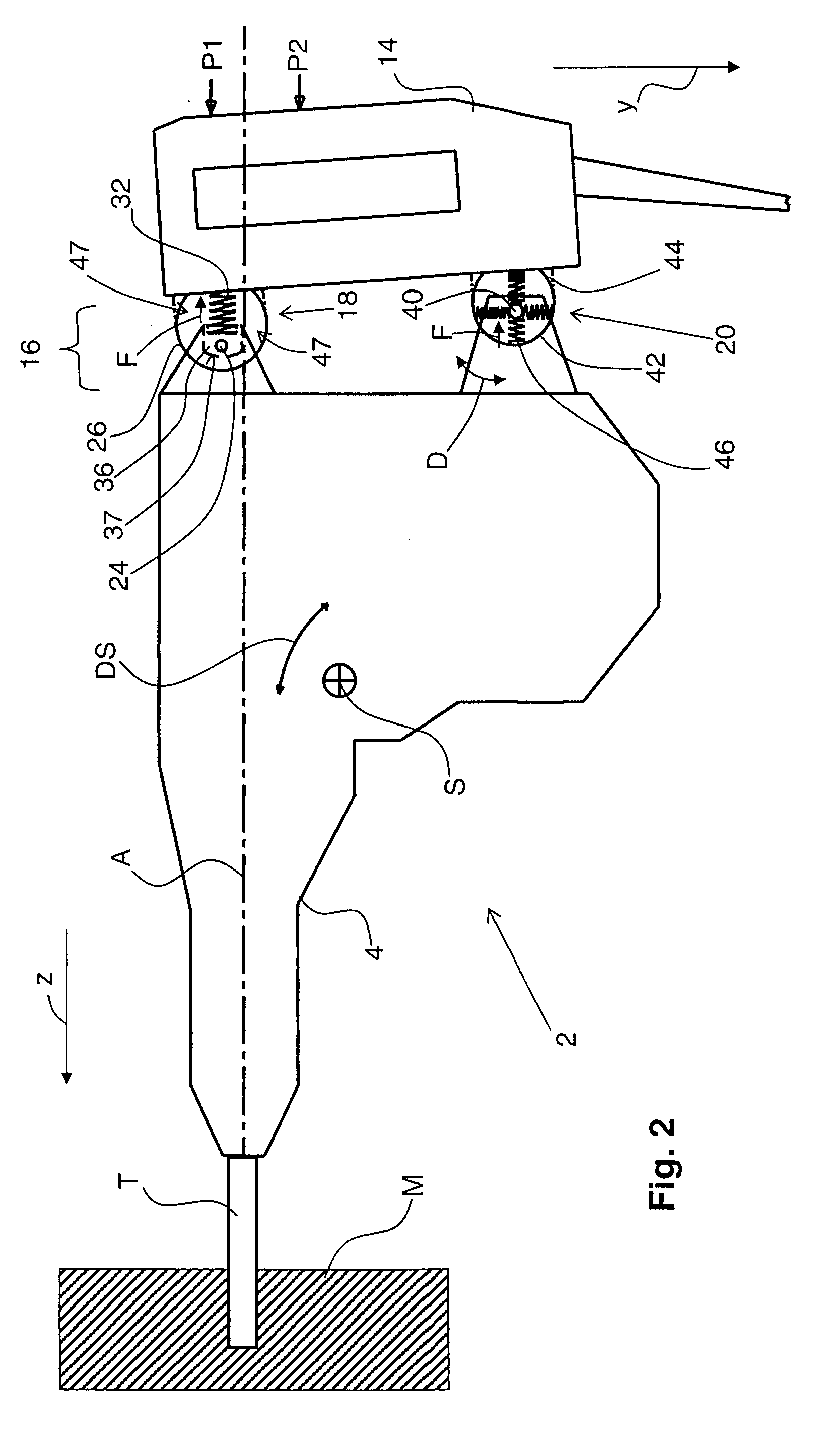
[0032] At the rear side 12 of the housing 4, a handle 14...


PUM

PropertyMeasurementUnit
Stiffnessaaaaaaaaaa

Abstract

A hand-held power tool includes a spring-mounted decoupling device (16) for supporting a tool handle (14) on the tool housing (4) and having a first spring-mounted support (18) and a second spring-mounted support (20) that is spaced from the operational axis (A) in a second direction (y) perpendicular to the first direction (z) further away than the first spring-mounted support (18) that has a smaller spring stiffness along the second direction (y) than along the first direction (z).

Description

BACKGROUND OF THE INVENTION [0001] 1. Field of the Invention [0002] The present invention relates to a hand-held power tool, in particular in form of an electrical combination hammer that can be alternatively used as a hammer drill or a chisel hammer and that includes a housing in which there is provided operational means that reciprocates along an operational axis spaced from the gravity center of the tool and extending parallel to a first direction which corresponds to the operational direction of the tool. E.g., the operational means can be formed as a percussion or impact piston of an electro-pneumatic percussion mechanism. The power tool further includes a handle supported on the housing by a spring-mounted decoupling device for preventing transmission of the housing vibrations to the handle. The decoupling device includes a first spring-mounted support and a second spring-mounted support in form of a pivotal support and that is spaced from the operational axis in a second dire...

Claims


Application Information

Patent Timeline
IPC IPC(8): B25F5/02B25D17/00
CPCB25D17/043B25D2211/003B25D2222/57B25F5/006B25D2250/245B25D2250/371B25D2222/69
Inventor FISCHER, AXELMEUER, ROLAND
Owner HILTI AG
Why Eureka
Try Eureka