Linear valve drive and valve

A linear actuator and driver technology, applied in the direction of lift valve, valve detail, valve device, etc., can solve the problems of reducing sealing closing force, occlusion, valve linear actuator or its driving unit stuck, etc., to achieve the effect of compact structure

Active Publication Date: 2016-10-26
BURKERT WERKE
View PDF7 Cites 0 Cited by
  • Summary
  • Abstract
  • Description
  • Claims
  • Application Information

AI Technical Summary

Problems solved by technology

The previously mutually determined drive system then has a greater error which can lead to a reduced seal closing force
[0004] Another

Method used


Image

  • Linear valve drive and valve
  • Linear valve drive and valve
  • Linear valve drive and valve

Examples


Embodiment Construction

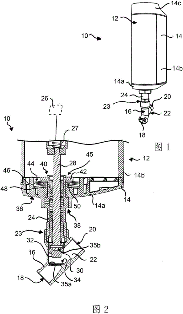
[0039] exist figure 1 A valve 10 is shown, which comprises a valve linear drive 12 with a drive housing 14 and a valve body 16 .

[0040] Valve body 16 has an inlet 18 and an outlet 20 . A flow channel 22 is formed between the inlet 18 and the outlet 20 , through which a fluid can flow and which can be provided by the valve 10 , in particular to regulate or control the flow of the fluid.

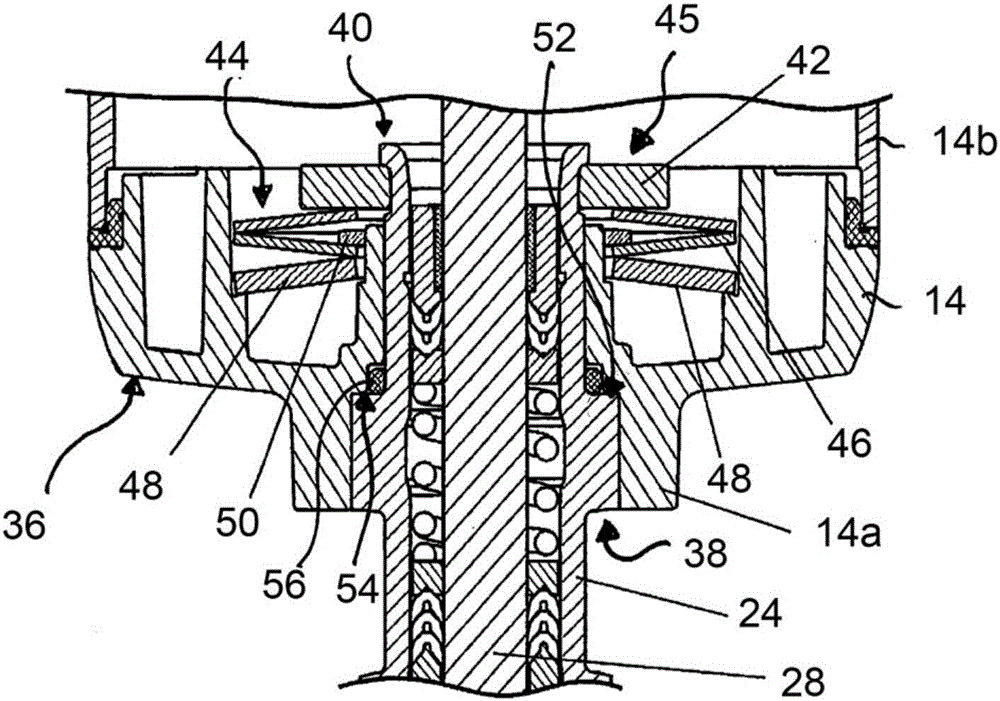
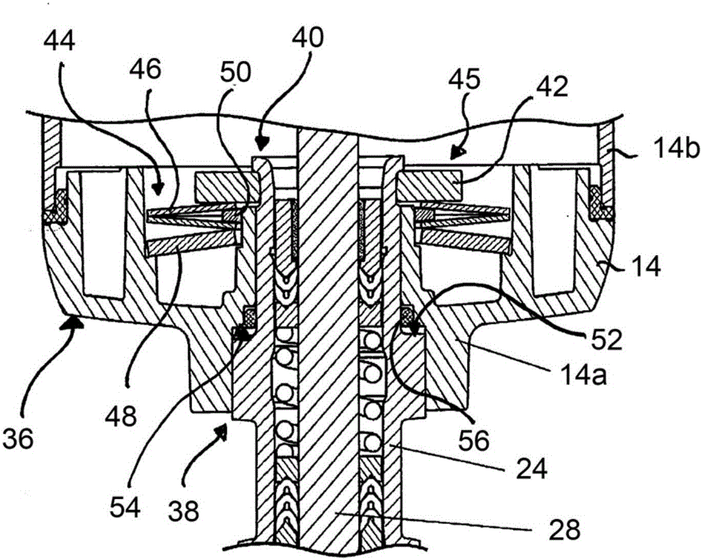
[0041] The valve body 16 is connected to the separately constructed valve linear drive 12 via a coupling point 23 which is arranged on a support unit 24 of the valve linear drive 12 . In the illustrated embodiment, the support unit 24 is formed separately from the drive housing 14 and separately from the valve body 16 , so that externally figure 2 , in which the valve 10 is shown in a sectional view in the region of the support unit 24 .

[0042] figure 2 The valve linear actuator 12 is shown with a drive unit 26, which is located at figure 2 is shown in dashed lines. The axially di...


PUM

PropertyMeasurementUnit
Spring rateaaaaaaaaaa

Abstract

A linear valve drive(12) for connection to a valve body(16) having a valve seat(34) and at least one flow passage(22) with at least one inlet(18) and at least one outlet(20), comprises a drive housing(14) with a drive unit(26) accommodated therein, an actuating element(28) axially shiftable by the drive unit and coupled with a valve closing element(32) to be pressed against the valve seat(34), and optionally closing the flow passage(22), and a supporting unit(24) surrounding the actuating element(28), which is designed to be attached to the valve body. A spring system(44) loaded by actuating the linear valve drive(12) is provided at the supporting unit, which in dependence on the compression path has different spring rates. Furthermore, a correspondingly equipped valve is described.

Description

technical field [0001] The invention relates to a valve linear drive for connection to a valve body and to a valve with a valve linear drive and a valve body. Background technique [0002] Valves for controlling or regulating fluids are known in the prior art which have a valve body and a valve linear drive which is constructed separately from the valve body, to which the valve body can be connected to form the valve. Typically, valve linear drives have a drive unit that adjusts an axially displaceable actuating member, on which the valve closure is typically provided or molded. Together with the valve closure, the drive unit can move the actuating member into the closed position, in which the valve closure rests on a valve seat built into the valve body and seals the valve seat so that fluid cannot flow through the valve. [0003] The problem is that the sealing closing force of the valve can be reduced when the valve linear drive is switched off or switched off. This pro...

Claims


Application Information

Patent Timeline
IPC IPC(8): F16K29/00F16K31/00F16K1/32
CPCF16K1/32F16K29/00F16K31/00F16K31/50F16K1/10F16K27/02F16K1/12
Inventor 克劳斯·贝克曼纽尔·克拉夫特于尔根·施密特
Owner BURKERT WERKE
Why Eureka
Try Eureka