Pedal-force simulator device

a simulator device and pedal force technology, applied in the direction of brake action initiation, foot actuation initiation, vehicle components, etc., can solve the problems of large spring stiffness, achieve the effect of easy production, high pressure force, and occupying little spa

Active Publication Date: 2019-05-02
ROBERT BOSCH GMBH
View PDF6 Cites 1 Cited by
  • Summary
  • Abstract
  • Description
  • Claims
  • Application Information

AI Technical Summary

Benefits of technology

[0004]According to the present invention, at least one disk spring is interposed between the coil springs and the axial stop and/or between the coil springs and the pressure plunger in each case. The pedal-force simulator device according to the present invention has the advantage that the disk spring is easy to produce, takes up little space and is able to be acted upon by a high pressure force. The disk spring is generally developed in the form of a truncated cone having a small axial extension so that it is able to be placed in a housing of the pedal-force simulator device without taking up much space. In addition, it usually has hi

Problems solved by technology

In addition, it usually has high mechanical preloading so that the disk spring will experience only a slight deflection when a high pressure force is exerted and g

Method used


Image

  • Pedal-force simulator device

Examples


Embodiment Construction

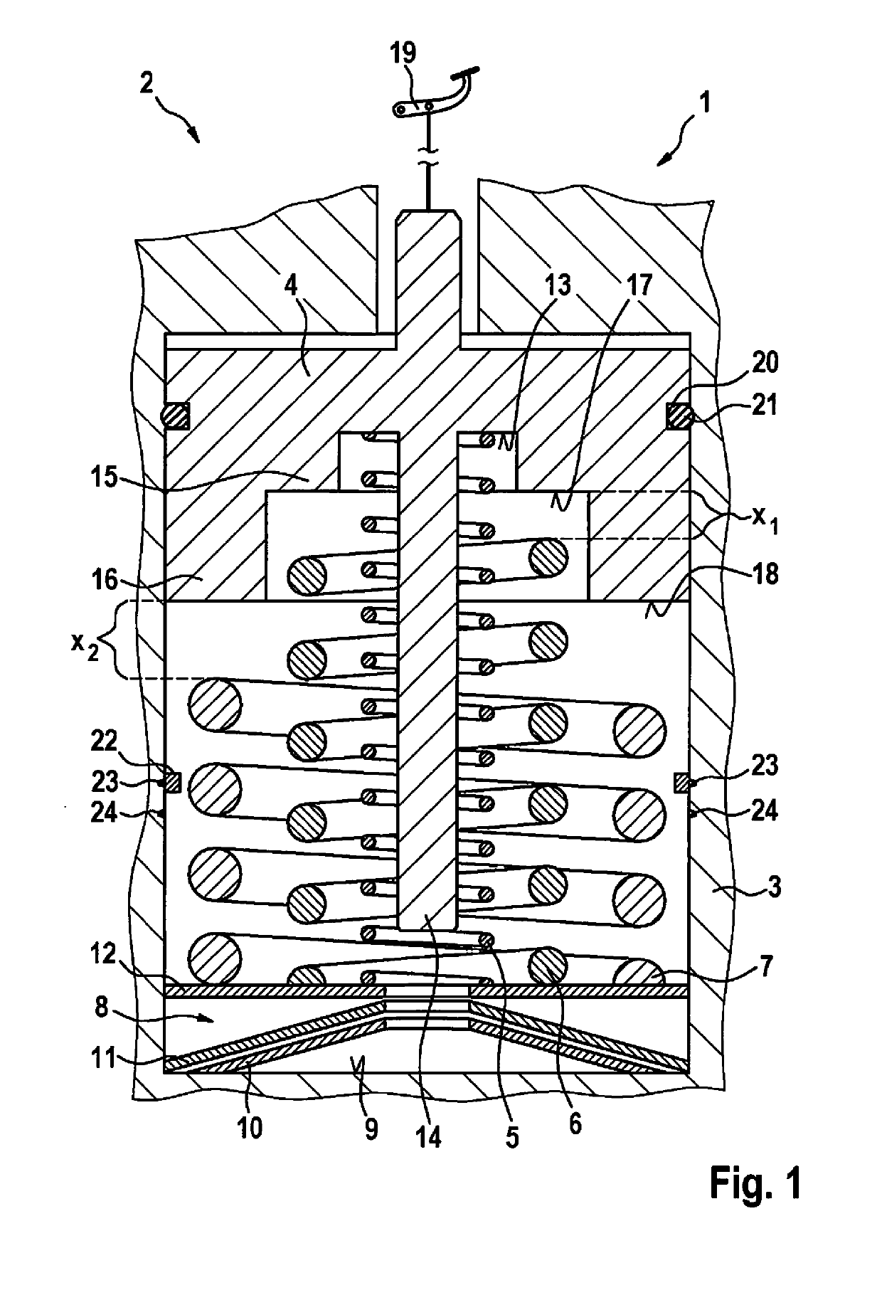
[0015]The single FIGURE shows a pedal-force simulator device 1 of a vehicle 2, which is not shown here, having a housing 3, which includes an actuable, axially displaceable pressure plunger 4, a first coil spring 5, a second coil spring 6, a third coil spring 7, and a disk-spring system 8. Disk-spring system 8 is interposed between coil springs 5, 6, 7 and an axial stop 9 situated at the bottom of housing 3.

[0016]Disk-spring system 8 has a first disk spring 10 and a second disk spring 11, the second disk spring 11 resting in parallel on first disk spring 10. An especially metallic bearing plate 12, which is displaceable in the axial direction, is disposed on second disk spring 11. On the one hand, it serves as a support surface for coil springs 5, 6, 7, and on the other hand it ensures that a pressure force exerted by pressure plunger 4 on coil springs 5, 6, 7 is transferred to disk-spring system 8 in a uniform manner.

[0017]Coil springs 5, 6, 7 are disposed coaxially to one another ...


PUM


Abstract

A pedal-force simulator device is described as having a housing in which an actuable pressure plunger is mounted in an axially displaceable manner, and having at least two coil springs, which are disposed parallel to one another between an end face of the pressure plunger and an axial stop of the housing. It is provided that at least one disk spring is interposed between the coil springs and the axial stop and/or between the coil springs and the pressure plunger in each case.

Description

FIELD OF THE INVENTION[0001]The present invention relates to a pedal-force simulator device, which has a housing in which an actuable pressure plunger is mounted in an axially displaceable manner; it also has at least two coil springs, which are disposed parallel to one another between an end face of the pressure plunger and an axial stop of the housing.[0002]In addition, the present invention relates to a vehicle, in particular a motor vehicle, which has such a pedal-force simulator device.BACKGROUND INFORMATION[0003]Pedal-force simulator devices of the type mentioned in the introduction are known from the related art. As a rule, they are used in vehicles that are equipped with electronic brake systems, which are also known as brake-by-wire brake systems. In this case the pedal-force simulator device simulates or generates a restoring force on the brake pedal in response to an operation of the brake pedal by a driver of the vehicle. The generated restoring force simulates a brake-p...

Claims


Application Information

Patent Timeline
IPC IPC(8): B60T8/32B60T8/40B60T7/04
CPCB60T8/3255B60T8/409B60T7/042B60Y2400/81
Inventor ANDERSON, CHRISVOGG, JUERGENKISTNER, MATTHIASSPROCQ, RAYNALDHANSMANN, SIMON
Owner ROBERT BOSCH GMBH
Why Eureka
Try Eureka