Rainproof recessed outlet box

a technology of outlet box and recessed outlet, which is applied in the direction of machine supports, installation of lighting conductors, coupling device connections, etc., to achieve the effect of reducing the cost of outlet box production, and reducing the size of the outlet box

Active Publication Date: 2005-11-15
ARLINGTON INDS
View PDF3 Cites 32 Cited by
  • Summary
  • Abstract
  • Description
  • Claims
  • Application Information

AI Technical Summary

Problems solved by technology

Cover members are typically molded of expensive impact resistant plastic to meet electrical code.

Method used


Image

  • Rainproof recessed outlet box
  • Rainproof recessed outlet box
  • Rainproof recessed outlet box

Examples


Embodiment Construction

[0031]The present invention comprises a recessed electrical box for securing an electrical device on the exterior wall of a building. The recessed electrical box has features that allow it to be easily recessed to the correct depth on either new construction or as a retrofit on the completed exterior surface existing building.

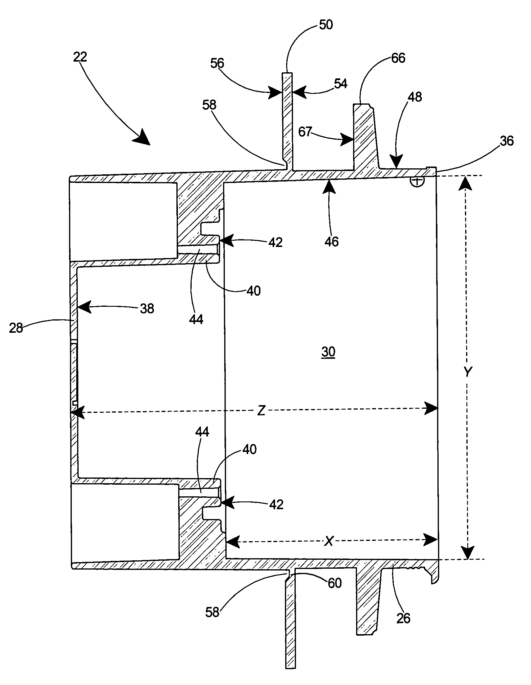
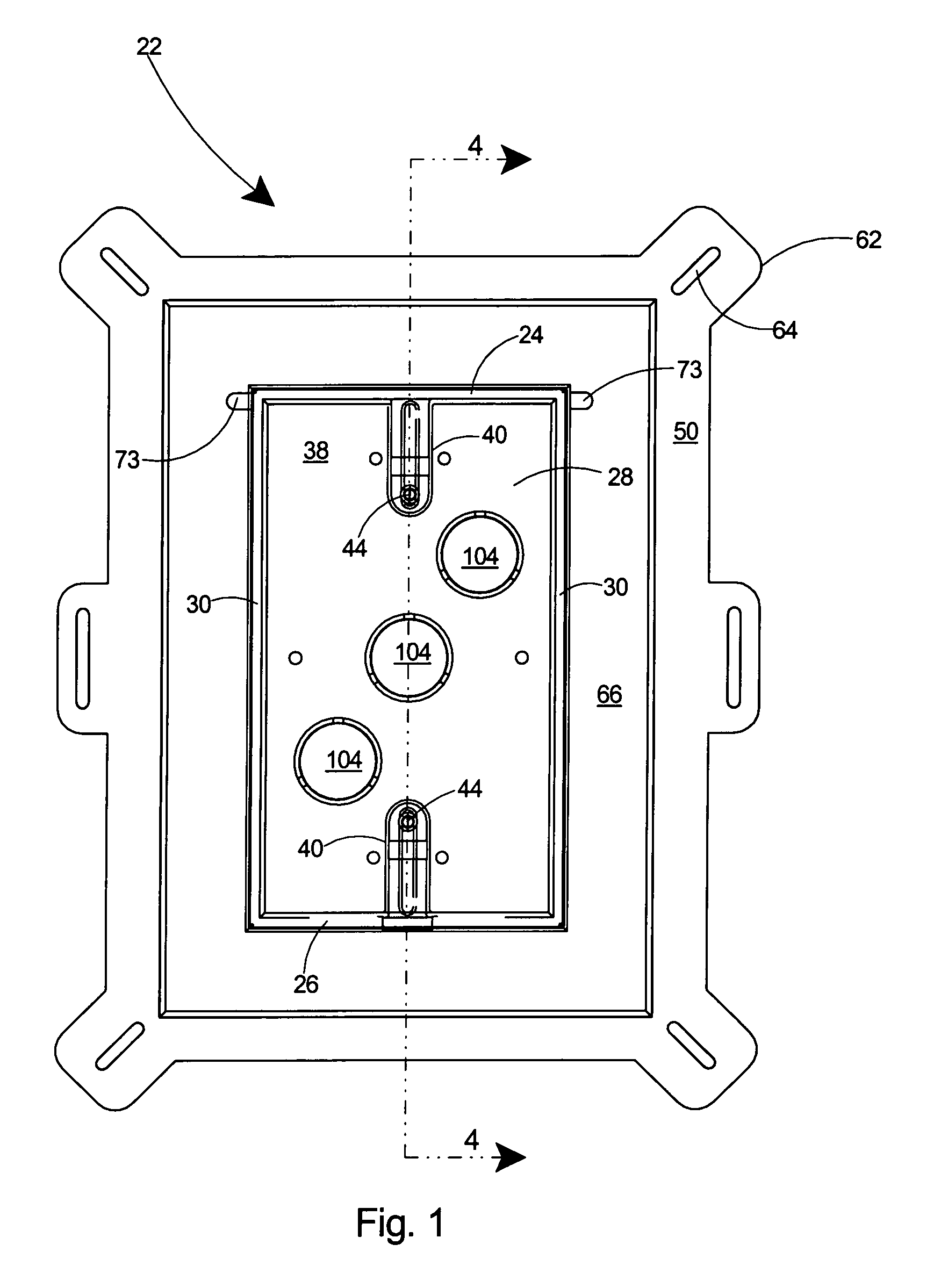
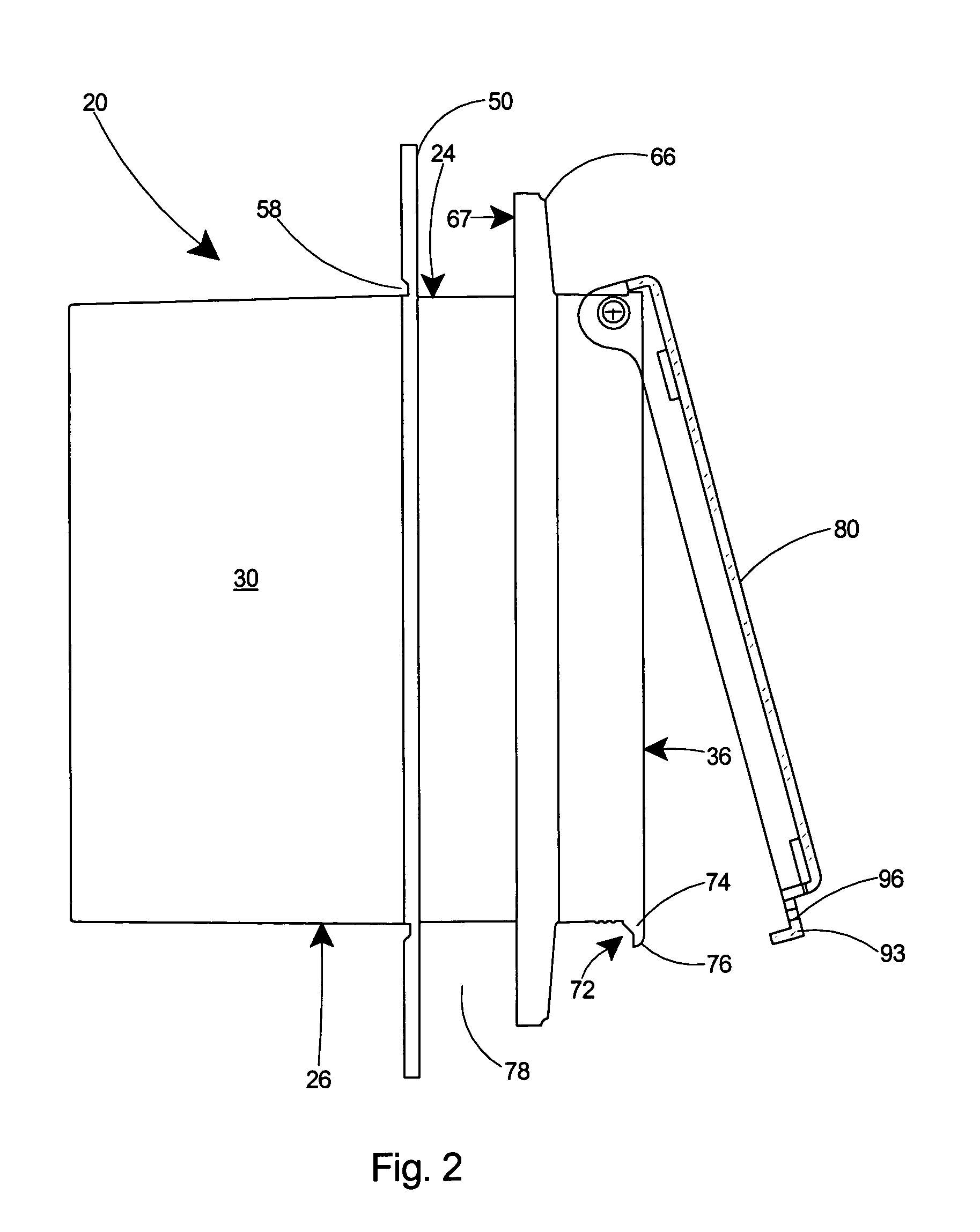
[0032]With reference to FIGS. 1–5, the box portion of a first and preferred embodiment of a recessed electrical box according to the present invention is shown. The recessed electrical box includes a box 22 having a top wall 24, a bottom wall 26, a back wall 28, side walls 30 extending orthogonally to the back wall 28, and a front opening 32 defining a cavity or enclosure 34 therein. The peripheral sidewalls 30 of the box 22 include a front edge 36 at the front opening 32. The box 22 is typically molded in one piece from plastic. Alternatively, the box 22 may be formed of metal.

[0033]The back wall 28, as shown in FIG. 1, includes a front surface 38. Integral bo...


PUM


Abstract

A recessed electrical box with a closeable cover member. The box may include a flange that serves as a positioning arrangement to recess the electrical box at the correct depth with respect to the surface in which it will be mounted. The recessed electrical box includes of two pieces, including a one-piece electrical box and a one-piece cover member. The cover member is of minimal size with respect to the electrical box to minimize the cost of construction. The electrical box can be installed on an exterior wall, including either as a retrofit on a finished building or as an installation on the wall of a building under construction. The outward extending flange may include an inner flange for positioning the recessed electrical box with respect to the outer surface of the substrate on a building under construction. The inner flange is removable to facilitate installation in a retrofit situation, in which the finish layer such as siding, stucco, or masonry is installed. The recessed electrical box may include a second, outer flange, for recessing the box at the correct depth with respect to a finished surface and to occlude from view the sidewalls of the box at their juncture with the finished surface. The one-piece electrical box includes side walls of that are spaced substantially the same distance apart from the front edge to the back wall of the box.

Description

[0001]This application is a Continuation-In-Part of U.S. patent application Ser. No. 11 / 009,116 filed Dec. 10, 2004 and still pending, which is a Continuation-In-Part of U.S. patent application Ser. No. 10 / 863,942 filed Jun. 9, 2004 and still pending.FIELD OF THE INVENTION[0002]This invention relates to electrical junction boxes and specifically to a recessed outlet box that secures an electrical device substantially behind the exterior of a building for accommodating and protecting a duplex outlet or other electrical device therein.BACKGROUND OF THE INVENTION[0003]Recessed electrical boxes for retrofitting on finished walls or for use in new construction were disclosed in co-pending U.S. application Ser. Nos. 10 / 863,942 and 11 / 009,116, commonly owned by the assignee of the present invention, the contents of which are incorporated herein by reference. The recessed electrical box disclosed in the co-pending applications comprised an electrical box having an inner enclosure for housin...

Claims


Application Information

Patent Timeline
Patent Type & Authority Patents(United States)
IPC IPC(8): H01H9/02H02G3/12
CPCH02G3/123Y10S248/906
Inventor GRETZ, THOMAS J.
Owner ARLINGTON INDS
Why Eureka
Try Eureka