Floor slab penetration structure and floor slab penetration hole repair method

a technology of floor slabs and penetration holes, which is applied in the direction of roof drainage, building repairs, roofing, etc., can solve the problems of difficult working to reach the ceiling of a floor, difficult to effectively discharge drainage water to the outside from multiple-story buildings, and the repair work of the penetration hole, etc., to achieve the effect of effective drainage water over long periods, simple structure, and easy repair

Active Publication Date: 2011-02-03
TOSHIBA PLANT SYSTEMS & SERVICES
View PDF4 Cites 8 Cited by
  • Summary
  • Abstract
  • Description
  • Claims
  • Application Information

AI Technical Summary

Benefits of technology

[0011]An object of the present invention is to provide a floor slab penetration structure and a method of repairing the floor slab penetration hole capable of effectively discharging drainage water over long periods and easily performing a repairing working with a simple structure in a concrete multiple-story building under construction.
[0025]The present invention having the aforementioned features can provide the floor slab penetration structure and the method of repairing the floor slab penetration hole in a temporary drainage system capable of effectively discharging drainage water over long periods with a simple configuration in a concrete multiple-story building under construction.

Problems solved by technology

Thus, it is difficult to effectively discharge the drainage water to the outside from the multiple-story building.
However, there are some buildings each of which has a high ceiling, a vaulted ceiling structure through several floors or like, in a case when it is required to repair and bury the penetration hole formed to a floor slab of a certain floor, there is caused a difficult working to approach a ceiling of a floor on a back side of a floor slab of the certain floor.
In such a case, there may cause a case that repairing working of the penetration hole and cure after the repairing working are not sufficiently performed.

Method used


Image

  • Floor slab penetration structure and floor slab penetration hole repair method
  • Floor slab penetration structure and floor slab penetration hole repair method
  • Floor slab penetration structure and floor slab penetration hole repair method

Examples


Embodiment Construction

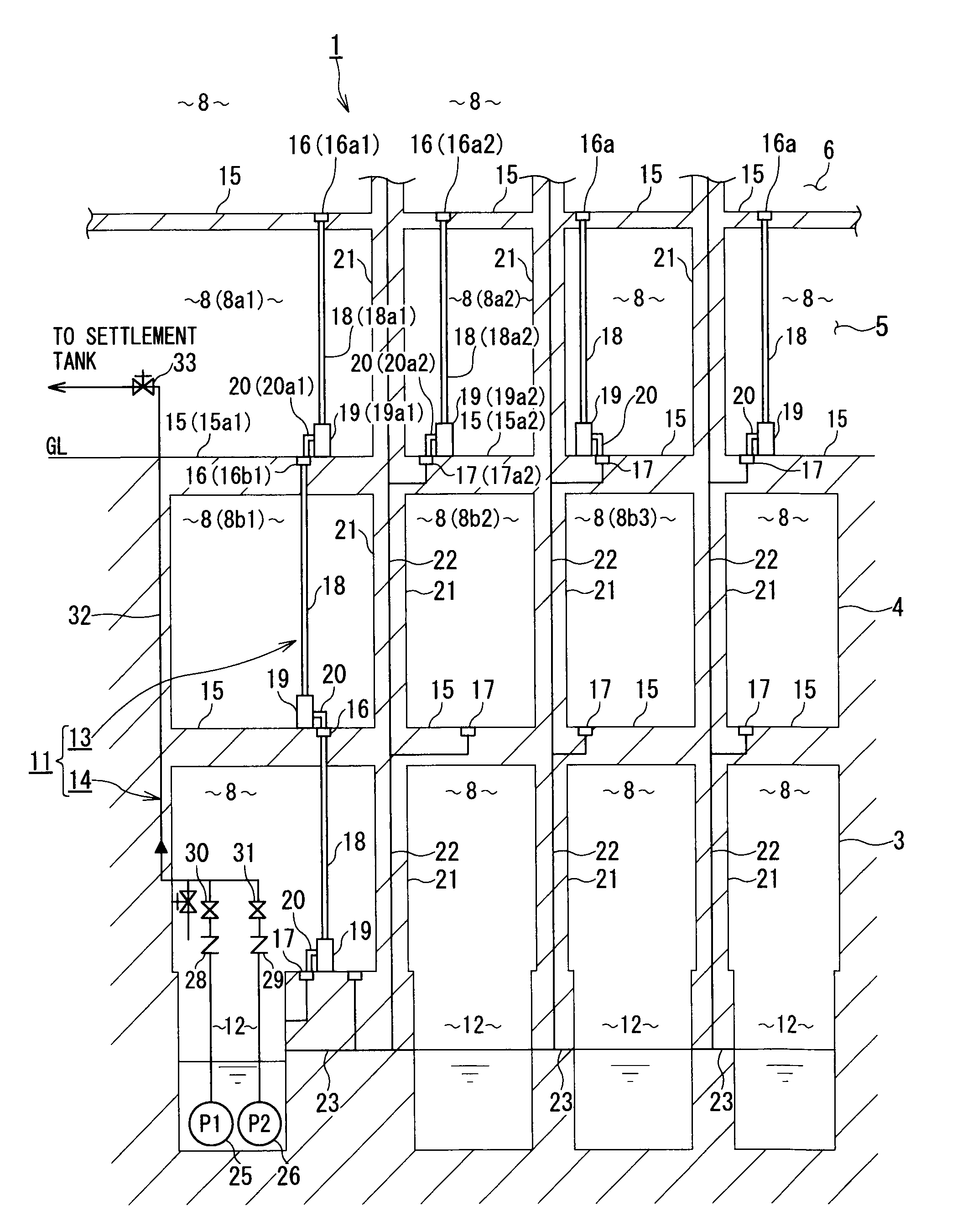
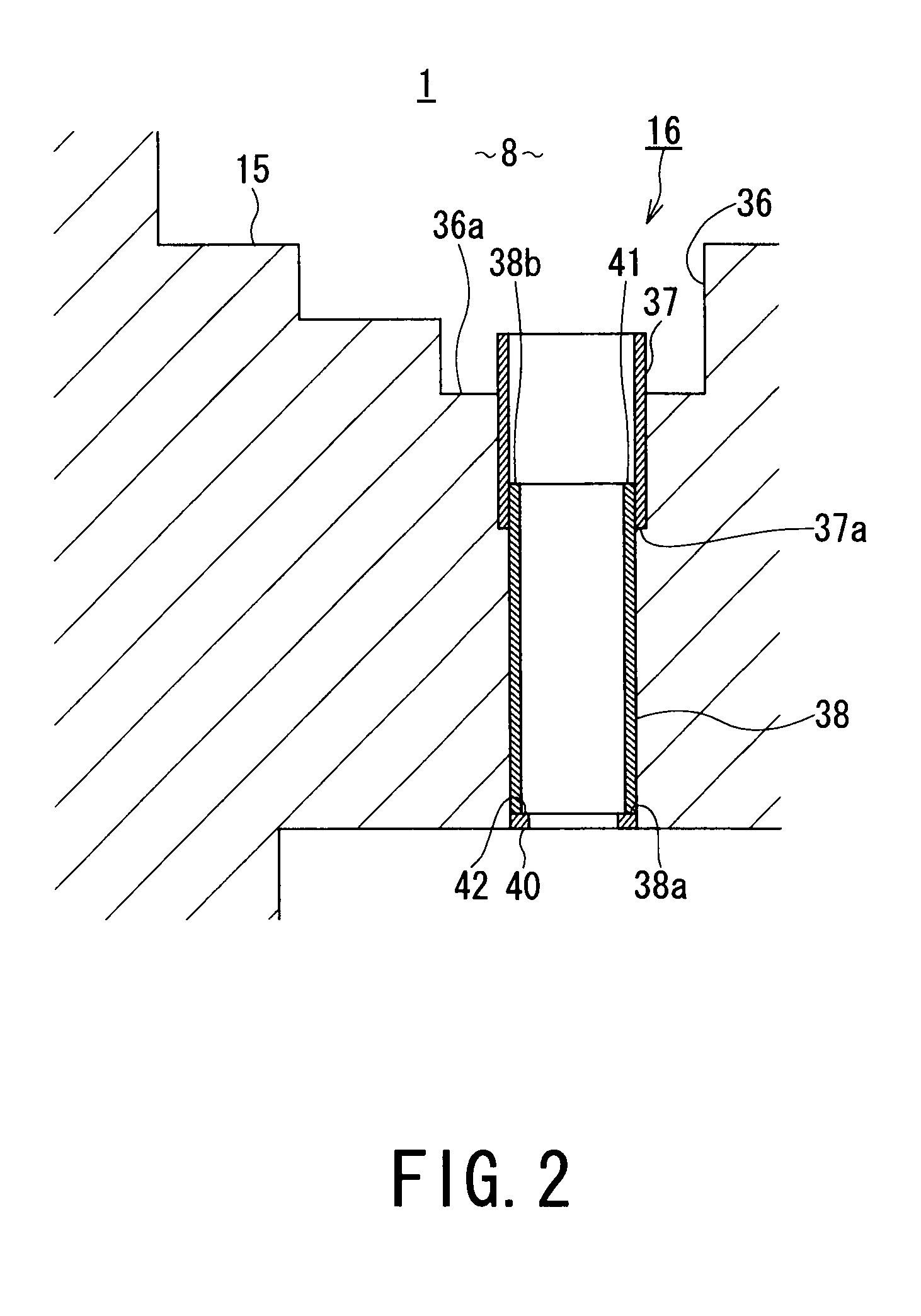
[0032]In the following, an embodiment of a temporary drainage system according to the present invention will be described with reference to FIGS. 1 to 5.

[0033]FIG. 1 shows a building under construction, in which a multiple-story building 1 is a reinforced concrete reactor building, which is of substantially square shape having about 100 m on each side in a plan view of the multiple-story building 1 in the present embodiment.

[0034]In the multiple-story building 1 shown in FIG. 1, a second basement floor 3, a first basement floor 4, and a first floor 5 have been already constructed, and a second floor 6 is under construction.

[0035]A plurality of rooms 8 are provided on each of the floors of the multiple-story building 1 under construction, and for example, the total number of rooms 8 is about 500 in a case where the multiple-story building 1 is the reactor building. The rooms 8 include an electrical room in which electrical equipment is housed (for example, the rooms 8 (8b2) and 8 (8b...


PUM


Abstract

As a temporary drainage equipment, a penetration hole is formed to a floor slab of a building under construction, the penetration hole is provided with a substantially cylindrical funnel portion opened to a floor surface of a room, a connection pipe is communicated to a bottom portion of the funnel portion, and a hose guide pipe is inserted to the lower end portion of the connection pipe. An inner flange portion is provided to the lower end portion of the hose guide pipe so as to be flash with a ceiling surface of the downfloor room.

Description

TECHNICAL FIELD[0001]The present invention concerns a temporary drainage technology for draining outside rain water that flows into a building under construction such as a reactor building of a nuclear power plant, and more specifically, relates to a floor slab penetration structure provided to the building under construction and also relates to a method of repairing a penetration hole.BACKGROUND ART[0002]When a concrete multiple-story (or multiple-floor) building such as a high-rise building and a reactor building is constructed, the building is constructed by casting concrete sequentially from a lowest floor. For example, casting working of concrete in a second floor portion is started after casting working of concrete in a first floor portion has been completed by constructing a slab in a ceiling portion of the first floor (a floor portion of the second floor).[0003]It is not preferable that rain water or the like flows into a lower floor that has already been constructed during ...

Claims


Application Information

Patent Timeline
Patent Type & Authority Applications(United States)
IPC IPC(8): E04G21/28E04B1/70E04F17/00
CPCE04D13/08E04D2013/0893E04G23/0203E04G21/28E04G15/061E04G23/004
Inventor HOSHI, ISAO
Owner TOSHIBA PLANT SYSTEMS & SERVICES
Why Eureka
Try Eureka