
Apparatus for supporting a stator end winding

a stator and end winding technology, applied in the direction of windings, electrical apparatus, dynamo-electric machines, etc., can solve the problems of reducing stress, and reducing the fatigue life of the respective stressing devi

Inactive Publication Date: 2005-11-15
ALSTOM TECH LTD
View PDF13 Cites 7 Cited by
  • Summary
  • Abstract
  • Description
  • Claims
  • Application Information

AI Technical Summary

Benefits of technology

The solution ensures optimal bracing and stress distribution across the stator winding, maintaining effective support during changing conditions and increasing the fatigue life of the supporting device by smoothing high-frequency disturbances.

Problems solved by technology

However, seating processes and the like may occur during operation of the stator which may have a disadvantageous effect on the stress acting on the winding and on the end winding.
However, this stress may decrease as a result of seating processes.
However, the compression springs cannot provide additional radial bracing, or bracing at right angles to the envelope surface, of the end winding, since the supporting rings absorb the spring forces in this direction.

Method used


Image

  • Apparatus for supporting a stator end winding
  • Apparatus for supporting a stator end winding
  • Apparatus for supporting a stator end winding

Examples


Embodiment Construction

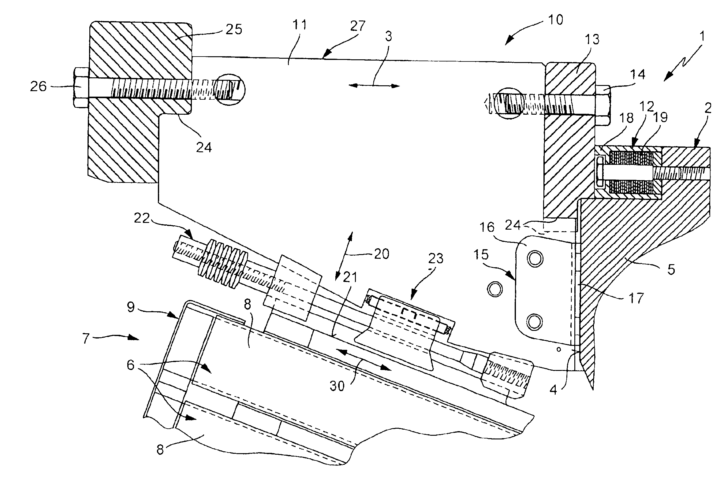
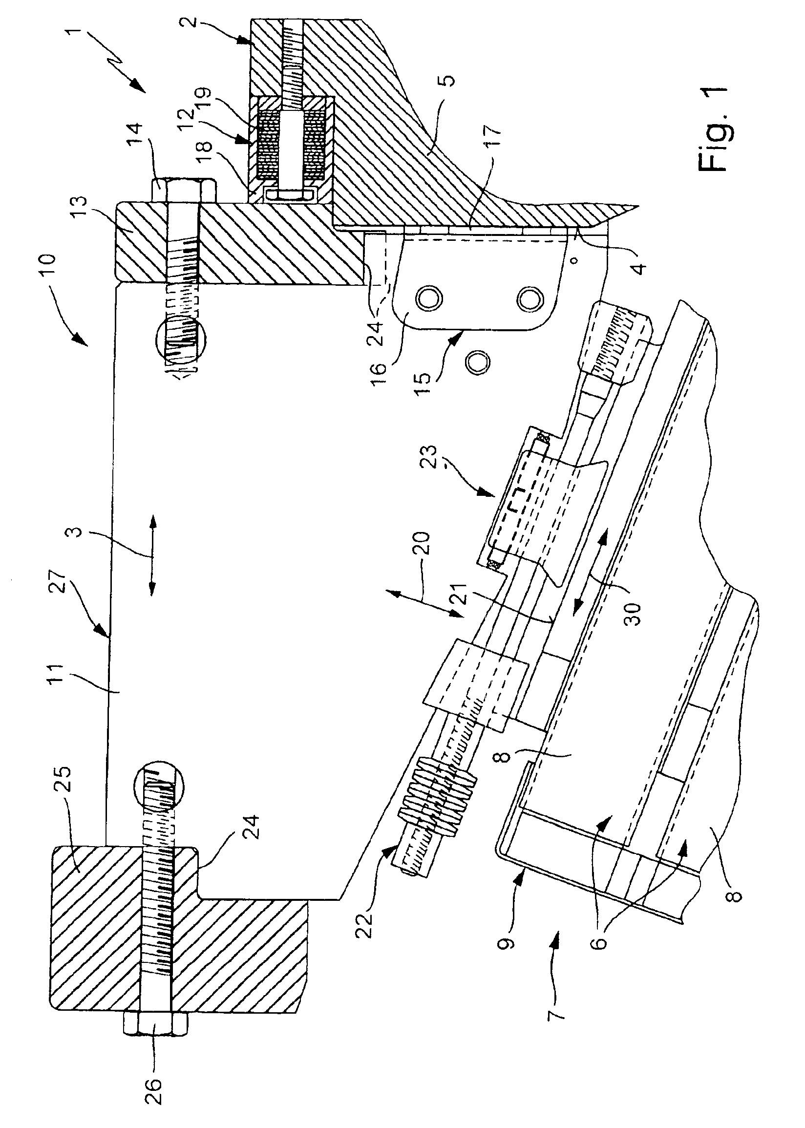
[0019]Referring As can be seen from FIG. 1, a stator 1 (only part of which is illustrated), in particular a generator stator for a generator (which is not illustrated apart from this), which is used, for example, in order to generate electrical power in a power station, has a core 2 (which is likewise illustrated only partially) which is illustrated in FIG. 1 such that its longitudinal center axis runs essentially horizontally. In this case, the longitudinal center axis of the core 2 is not located on the surface of the drawing in FIG. 1, but, for illustrative purposes, is symbolized by a double-headed arrow 3, which runs parallel to the longitudinal center axis of the core 2 and thus represents the axial direction.

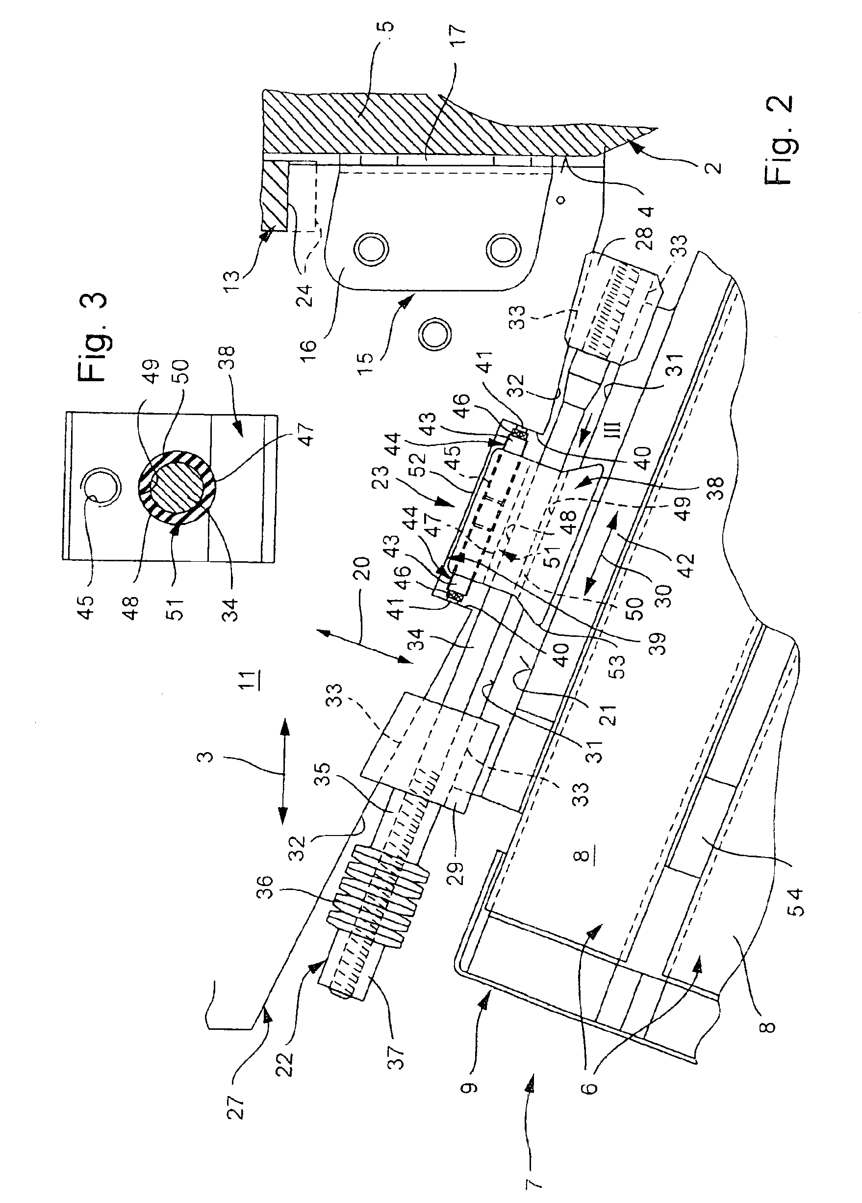
[0020]The core 2 has an axial end face 4 which in this case is in the form of a pressure plate 5 on the core 2. Two such pressure plates 5, which are arranged at the two axial ends of the core 2, can be used to brace metal-laminate segments, which are arranged between the...


PUM


Abstract

An apparatus (10) for supporting a winding (7) on a stator (1), in particular on a generator stator in a power station. The winding (7) has an end winding (9) which is supported axially on the core (2) of the stator (1) via winding supports (11) of the supporting apparatus (10). The winding supports (11) are supported on the end winding (9) via a stressing device (22), at right angles to an envelope surface (21). In order to improve the axial position between the winding support (11) and the end winding (9) during operation of the stator (1), a coupling device (23) is provided which allows relative movements between the end winding (9) and the winding support (11) in the circumferential direction and at right angles to the envelope surface (21), and prevents such relative movements in an envelope line direction (30).

Description

[0001]This application claims priority under 35 U.S.C. §119 to German application no. 103 30 523.8, filed Jul. 5, 2003, the entirety of which is incorporated by reference herein.BACKGROUND OF THE INVENTION[0002]1. Field of the Invention[0003]The present invention relates to an apparatus for supporting a winding on a stator, in particular on a generator stator in a power station.[0004]2. Brief Description of the Related Art[0005]Normally, a stator, in particular a generator stator in a power station, has a core as well as a winding which has two or more winding bars. The ends of these winding bars are passed out of the core at at least one axial end face of the core of the stator, and are thus bent around and connected to one another such that they form an end winding on the end face of the core, which widens in the form of a funnel or in the form of a cone as the distance from the core increases. For operation of the stator, this end winding must be supported in the axial direction ...

Claims


Application Information

Patent Timeline
Patent Type & Authority Patents(United States)
IPC IPC(8): H02K3/50
CPCH02K3/505
Inventor HEDIGER, DANIELLUKACIC, HRVOJEMADLE, DUNCANSTALLONE, FRANCESCOZIEGLER, ALFRED
Owner ALSTOM TECH LTD
Learn More