Power line communication system and method of using the same

a power line communication and power distribution system technology, applied in powerline communications applications, wireless systems/telephones, instruments, etc., can solve the problems of limiting the strength of data signals that can be injected onto power lines, many challenges to overcome, and overhead power lines are not designed to provide high speed data communication,

Inactive Publication Date: 2005-11-15
CURRENT TECH
View PDF387 Cites 426 Cited by
  • Summary
  • Abstract
  • Description
  • Claims
  • Application Information

AI Technical Summary

Benefits of technology

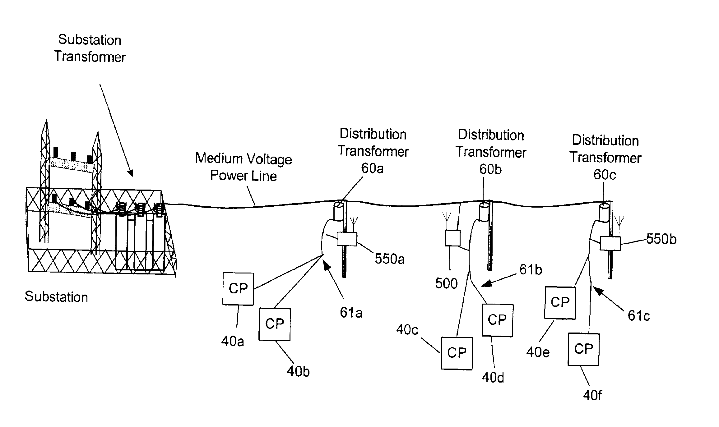
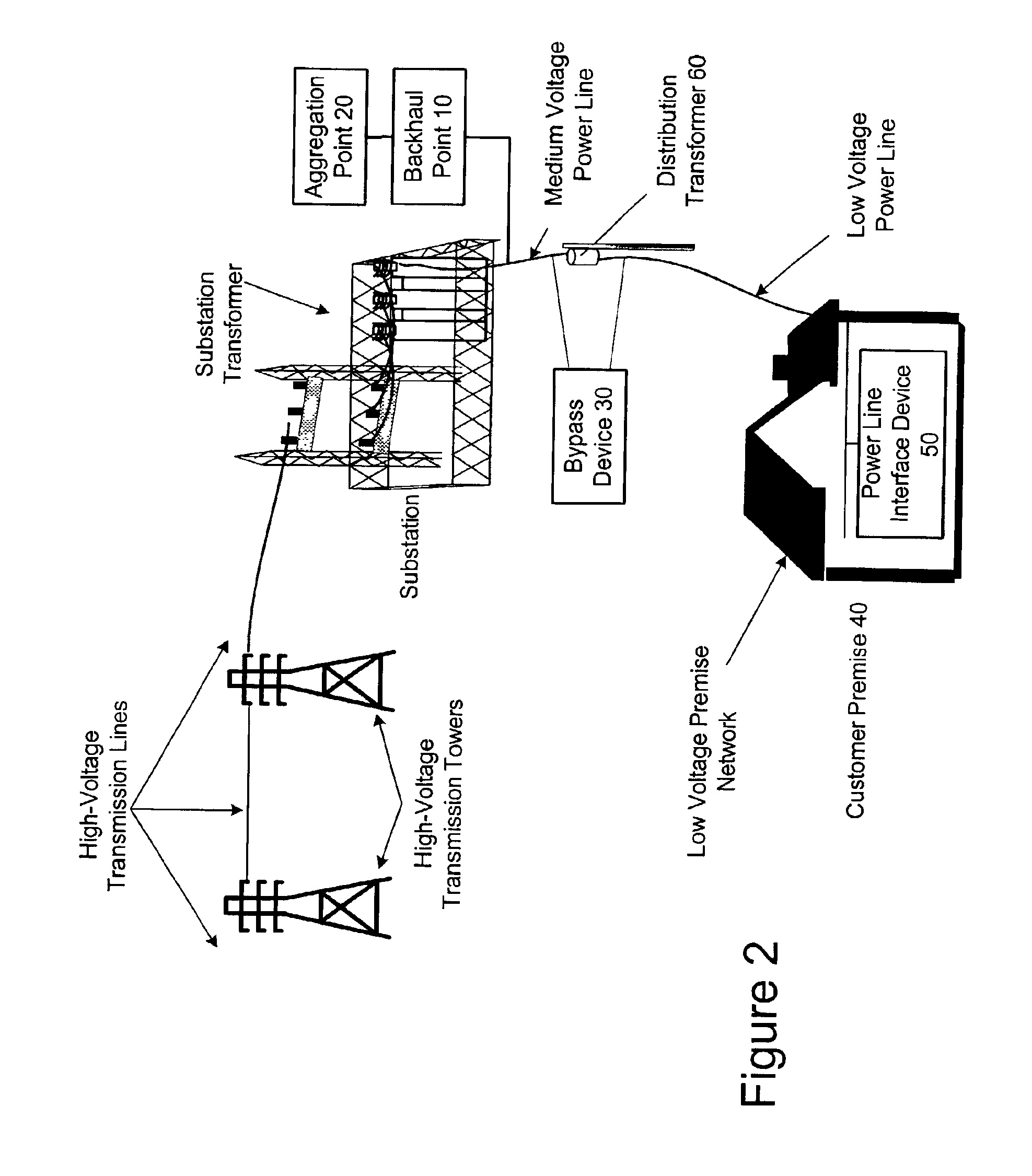
[0009]The present invention provides a communication system for use with a power line distribution system. One embodiment of the present invention comprises a communication system for communicating data through a power distribution system having a medium voltage power line and low voltage power line and comprises a first device comprising a first wireless transceiver, a first modem in communication with the first wireless transceiver and the medium voltage power line. The system may also comprise a second device comprising a second wireless transceiver in wireless communication with the first wireless transceiver, and a second modem in communication with the second wireless transceiver and the low voltage power line.

Problems solved by technology

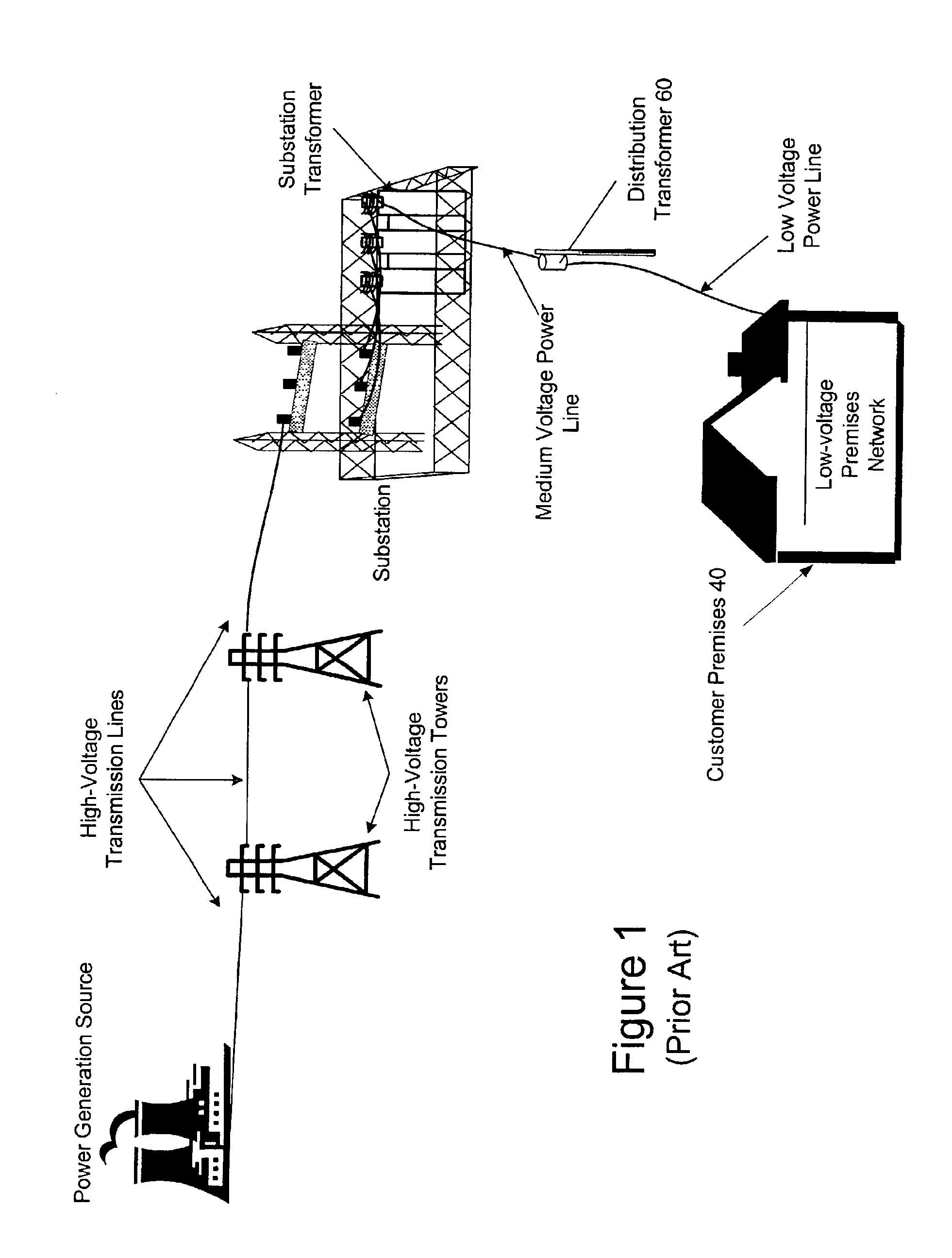
While the concept may sound simple, there are many challenges to overcome in order to use power lines for data communication.
Overhead power lines are not designed to provide high speed data communications and are very susceptible to interference.
Additionally, federal regulations limit the amount of radiated energy of a power line communication system, which therefore limits the strength of the data signal that can be injected onto power lines (especially overhead power lines).
Power system transformers are one obstacle to using power distribution lines for data communication.
As such, power line communication systems face the challenge of communicating the data signals around, or through, the distribution transformers.

Method used


Image

  • Power line communication system and method of using the same
  • Power line communication system and method of using the same
  • Power line communication system and method of using the same

Examples


embodiment

Bypass Device Embodiment

[0046]The following description is for a communication device of the present invention that is embodied as a BD. In particular, the embodiment described immediately below is a BD for bypassing a pole-mounted transformer. The present invention is equally applicable for use in bypassing other types of transformers (such as pad mount and underground) and in other applications (such as repeaters and backhaul points) with minor modifications that will be evident to those skilled the art.

[0047]The BD described herein, which is an example embodiment of the present invention, provides bi-directional communications and includes the functional block diagrams shown in FIG. 4. In particular, in this embodiment of the BD 100 includes a MV power line interface (MVI) 200, a controller 300, and a LV power line interface (LVI) 400. The BD 100 is controlled by a programmable processor and associated peripheral circuitry, which form part of the controller 300. The controller 30...


PUM


Abstract

The communication system of one embodiment is for communicating data through a power distribution system having a medium voltage power line and low voltage power line and comprises a first device comprising a first wireless transceiver, a first modem in communication with the first wireless transceiver and the medium voltage power line. The system may also comprise a second device comprising a second wireless transceiver in wireless communication with the first wireless transceiver; and a second modem in communication with the second wireless transceiver and the low voltage power line.

Description

CROSS REFERENCE TO RELATED APPLICATIONS[0001]This application is a continuation-in-part and claims priority under 35 U.S.C. §120 to U.S. patent application Ser. No. 10 / 315,725, filed Dec. 10, 2002, entitled “A Power Line Communication Apparatus and Method of Using the Same,” which is a continuation-in-part and claims priority under 35 U.S.C. §120 to U.S. patent application Ser. Nos. 10 / 075,708 and 10 / 075,332 (which both were filed Feb. 14, 2002, which both claim priority to U.S. Provisional Patent Application Ser. No. 60 / 268,519 and of U.S. Provisional Patent Application Ser. No. 60 / 268,578, both filed Feb. 14, 2001), is a continuation-in-part and claims priority under 35 U.S.C. §120 to U.S. patent application Ser. No. 09 / 915,459 filed Jul. 26, 2001 now abandoned (which claims priority to U.S. Provisional Patent Application Ser. No. 60 / 268,519 filed Feb. 14, 2001), is a continuation-in-part and claims priority under 35 U.S.C. §120 to U.S. patent application Ser. No. 09 / 912,633 filed...

Claims


Application Information

Patent Timeline
Patent Type & Authority Patents(United States)
IPC IPC(8): G02B6/48G02B6/46H04B3/54H04B3/56G02B6/42H04BH04M11/04
CPCG02B6/483H04B3/54H04B3/542H04B3/56G02B6/4246H04B2203/5441H04B2203/5466H04B2203/5487
Inventor MOLLENKOPF, JAMES DOUGLASBERKMAN, WILLIAM H.YANEY, DAVID STANLEYKLINE, PAUL A.
Owner CURRENT TECH
Why Eureka
Try Eureka