Multi-person shared display device

a display device and multi-person technology, applied in the field of display devices, can solve the problems of forming three-dimensional images, unresolved technical problems preventing full color, high resolution, real-time viewing, and inability to freely change the viewpoint, and achieve the effect of reducing errors

Inactive Publication Date: 2005-11-15
JAPAN SCI & TECH CORP
View PDF13 Cites 59 Cited by
  • Summary
  • Abstract
  • Description
  • Claims
  • Application Information

AI Technical Summary

Benefits of technology

[0014]The proposed multi-person shared display device uses a display mask in which a hole is formed and covers the display device so as to hide portions besides the hole, allowing different display regions upon the display device to be set in accordance with the viewpoint position within real space of each user. This makes it possible to perform display in response to viewpoint movements of a plurality of users.

Problems solved by technology

Moreover, not only is it being used for that which actually exists and can be actually seen, but also it is being used to visualize temperature distribution, airflow, and electromagnetic fields, which cannot actually be seen.
These techniques of forming three-dimensional images, as typified by holography, still have unresolved technical issues preventing full color, high resolution, and real time viewing.
However, it is not possible to freely change the viewpoint from which the three-dimensional object shown is viewed to coordinate with the user's movements using this technique by itself.
However, with this technique, the number of users for which viewpoint movement within real-space can be reflected in the virtual world is limited to one person for each display.
There is no display method appropriate for a plurality of viewpoints when a plurality of users shares a common display.
However, with the former, as the number of viewers increases, the allowable lower frequency limit of the composition of the three-dimensional view is not reached (the number of frames decreases), the display frequency is in inverse proportion to the number of users, which cause problems such as flickers to occur.
With the latter, the number of display devices matching the number of users or a large-scale device is required, which is problematic in terms of price.
However, if a plurality of people try to view the same three-dimensional video without distortion, since the display switches back and forth between the right eye and left eye video of a plurality of positions, the time interval between displaying an image for each person that has increased the number of time divisions becomes longer, causing a flicker to be sensed.

Method used


Image

  • Multi-person shared display device
  • Multi-person shared display device
  • Multi-person shared display device

Examples


Embodiment Construction

[0029]Embodiments of the present invention are described forthwith while referencing the drawings.

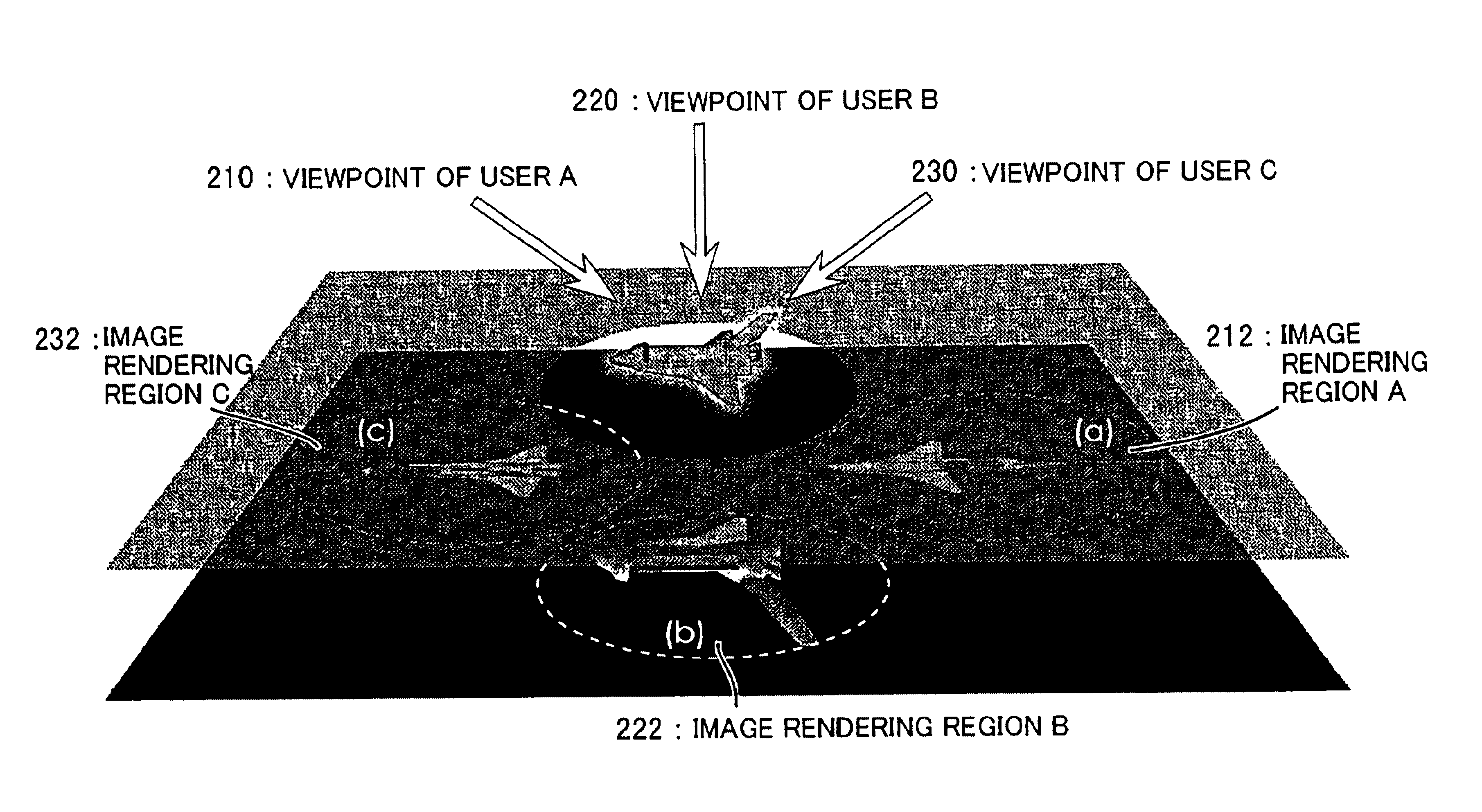
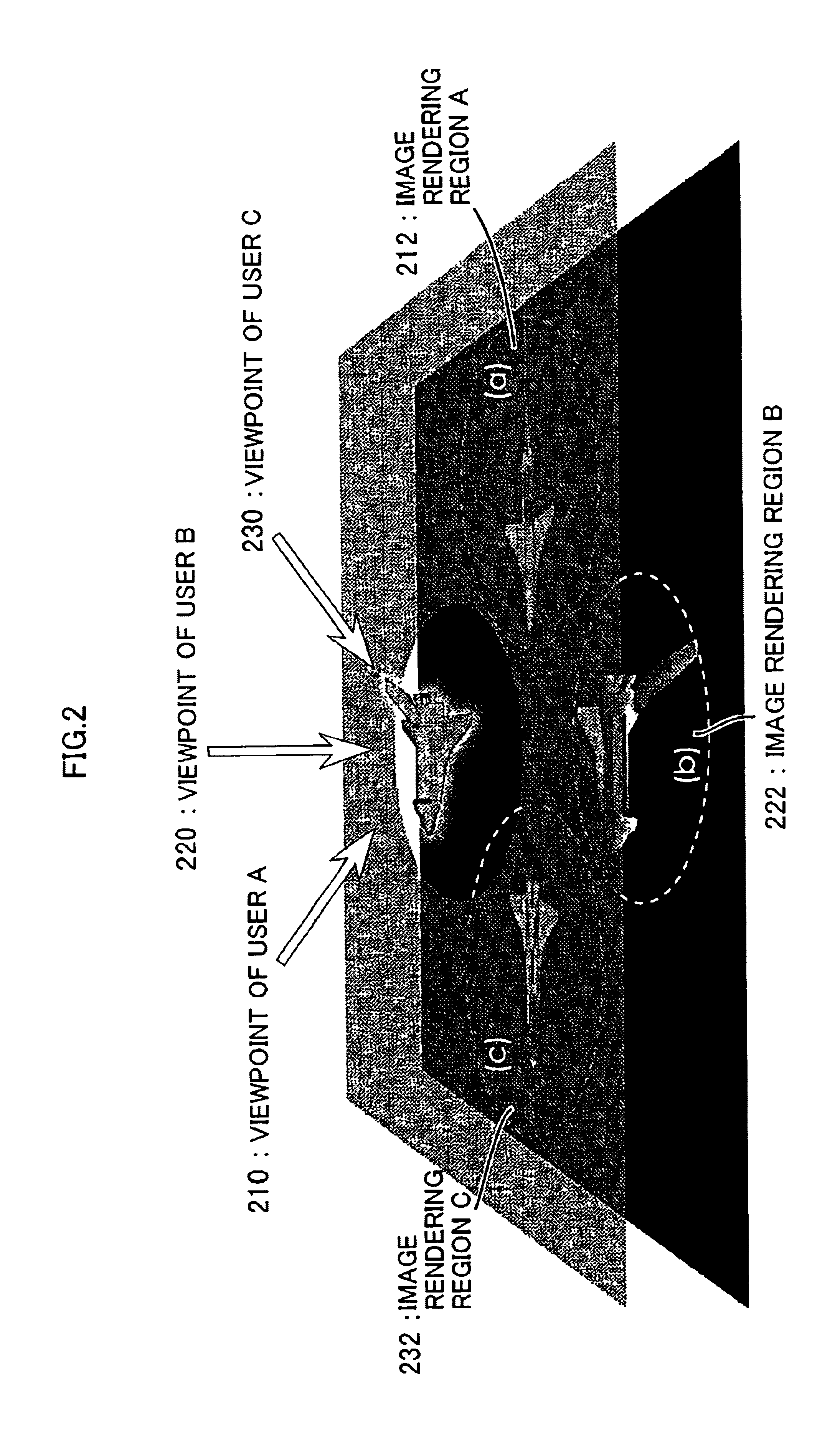
[0030]To begin with, an example where a three-dimensional image is shown with a multi-person shared three-dimensional display device is described.

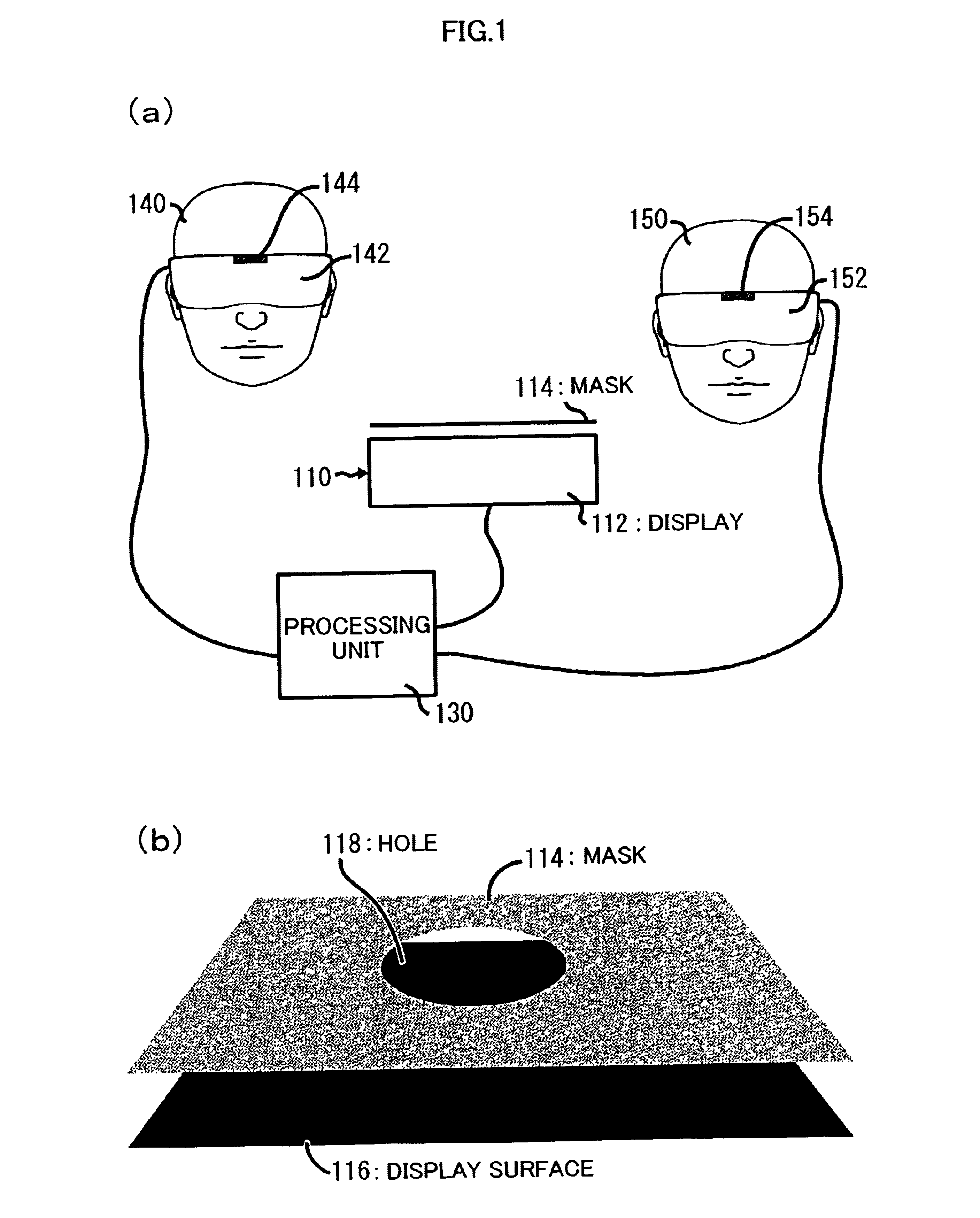
[0031]FIG. 1(a) is a diagram showing a configuration of a multi-person shared three-dimensional display device according to an embodiment of the present invention. In FIG. 1(a), two users 140 and 150 of a multi-person shared three-dimensional display device each have on liquid crystal shutter glasses 142, 152, respectively, and also have a respective position sensor 144, 154 attached. The users view an image displayed upon a display screen 110 via the liquid crystal shutters. The liquid crystal shutter glasses 142, 152, position sensors 144, 154, and display device 110 are connected to a processing device 130. In conformity with the input from the position sensors, the processing apparatus 130 displays an image upon the display at a region cor...


PUM


Abstract

The object of the present invention is to provide a multi-person shared display device with which a display device can be shared by a plurality of persons. For this purpose, a display device of the present invention is configured by a large screen display 112 and a display mask 114, which covers and hides a portion thereof. The display mask 114 is disposed at a position only an appropriate distance away from a display surface 116. The display mask 114 has a hole 118, and only through that portion can the display surface 116 of display 112 be seen. By introducing such display mask 114, the region visible upon the display surface differs depending on the viewpoint position of the user. As a result, it becomes possible to provide different content for every user.

Description

TECHNOLOGICAL FIELD[0001]The present invention relates to a display device. In particular, it is related to display device allowing a plurality of users to share a common display device.BACKGROUND TECHNOLOGY[0002]In recent years, computers and the environment surrounding computers has been rapidly expanding. Together with such expansion, technology using computers is widely used and has become commonplace so that these days computers can be seen in every aspect of our daily lives.[0003]Within this expansion of the environment surrounding computers, technology related to virtual reality is also expanding. The increasing speed of computers has made it possible to bring the construction of complicated virtual environments to even greater heights. Currently, this virtual reality technology has come to be used in various fields, and objects realized in virtual worlds are wide-ranging from large scale to small scale and high definition, such as outer space, metropolitan areas, environment...

Claims


Application Information

Patent Timeline
Patent Type & Authority Patents(United States)
IPC IPC(8): G02B27/01G02B27/22G06F3/00H04N13/00G06F3/01
CPCG02B27/017G02B27/0172G02B27/2228G06F3/011H04N13/0418H04N13/047H04N13/0497G02B2027/0178H04N13/0285H04N13/0436H04N13/044H04N13/32H04N13/344H04N13/368H04N13/339H04N13/286H04N13/398G02B30/34
Inventor KITAMURA, YOSHIFUMIKISHINO, FUMIOMASAKI, TOSHIHIROKONISHI, TAKASHIGE
Owner JAPAN SCI & TECH CORP
Why Eureka
Try Eureka