Method, system, and program for selecting devices to use to execute selected tasks in a graphical user interface

a graphical user interface and task technology, applied in computing, instruments, electric digital data processing, etc., can solve the problems of complicated user interaction, inability to view source and destination points of potential object transfers simultaneously on the screen, etc., and achieve high throughput printing operations.

Inactive Publication Date: 2005-11-15
RICOH KK
View PDF3 Cites 10 Cited by
  • Summary
  • Abstract
  • Description
  • Claims
  • Application Information

AI Technical Summary

Problems solved by technology

Along with this benefit comes the problem of how to present the great number and variety of available functions to the interactive operator or user in display interfaces which are relatively easy to use.
This complicates user interaction, particularly in situations where the user needs to view and compare objects or properties of objects which are in portions of the tree remote from each other.
Also, when the user needs to move objects from one part of a tree to another part of the tree, the inability to view source and destination points of the potential object transfer simultaneously on the screen complicates the user interaction.

Method used


Image

  • Method, system, and program for selecting devices to use to execute selected tasks in a graphical user interface
  • Method, system, and program for selecting devices to use to execute selected tasks in a graphical user interface
  • Method, system, and program for selecting devices to use to execute selected tasks in a graphical user interface

Examples


Embodiment Construction

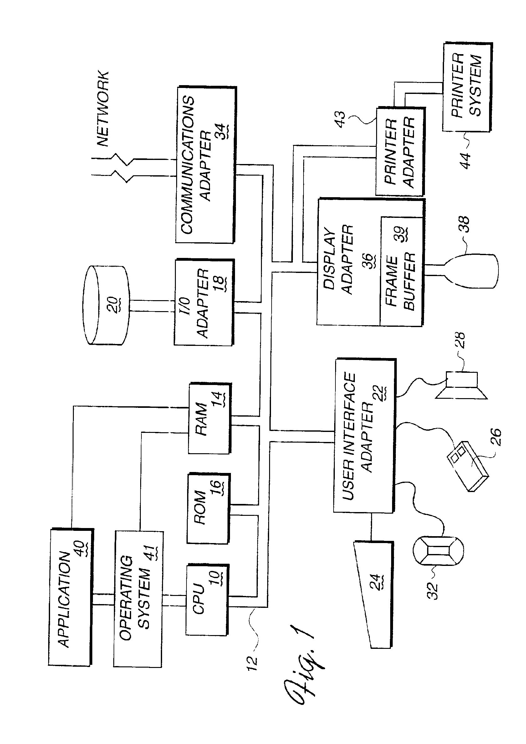
[0018]Referring to FIG. 1, a typical data processing system is shown which may function as the computer controlled display terminal used in implementing the tree view and detail view functions of the present invention. A central processing unit (CPU), such as one of the PC microprocessors available from International Business Machines Corporation, is provided and interconnected to various other components by system bus 12. An operating system 41 runs on CPU 10, provides control and is used to coordinate the function of the various components of FIG. 1. Operating system 41 may be one of the commercially available operating systems such as DOS or the OS / 2 operating system available from International Business Machines Corporation (OS / 2 is a trademark of International Business Machines Corporation); Microsoft Windows 95(™) or Windows NT(™), as well as Unix and AIX operating systems. A programming application for displaying multiple hierarchical tree views and for presenting detail view...


PUM


Abstract

A data processing controlled display system for the interactive display and control of a hierarchical trees of elements or objects in which multiple tree views are presented to the user. The objects in the views are selectable to display detail views of the objects, particularly attributes of the child objects of the selected parent object. The multiple tree views may be of different portions of the same tree or of different trees. The tree views are thus available for side by side comparison and detailed study, after which the system provides the capability to transfer objects from tree view to tree view, e.g. by drag and drop means.

Description

[0001]This application is a continuation of application Ser. No. 09 / 052,858 filed Mar. 31, 1998, now U.S. Pat. No. 6,281,896.CROSS-REFERENCE TO RELATED COPENDING PATENT APPLICATIONS[0002]The following patent applications which are assigned to the assignee of the present invention cover subject matter related to the subject matter of the present invention: “Data Processor Controlled Display System With a Plurality of Selectable Basic Function Interfaces for the Control of Varying Types of Customer Requirements and With Additional Customized Functions”, Ser. No. 09 / 053,210; “Data Processor Controlled Display System With a Plurality of Switchable Customized Basic Function Interfaces for the Control of Varying Types of Operations”, Ser. No. 09 / 053,214; “Data Processor Controlled Display System for the Control of Operations With Control Properties Which are Selectably Constant or Variable”, Ser. No. 09 / 053,207; “Data Processor Controlled Display Interface With Tree Hierarchy of Elements ...

Claims


Application Information

Patent Timeline
Patent Type & Authority Patents(United States)
IPC IPC(8): G06F3/14G06F7/00G09B5/00G06F3/0484
CPCG06F3/04842
Inventor ALIMPICH, CLAUDIAJEFFCOAT, BENJAMIN NELSONNEUHARD, DEBORAH ELIZABETHVIGIL, LUANA LINDAWITTIG, JAMES PHILIP JOHN
Owner RICOH KK
Why Eureka
Try Eureka