Image processor, image processing method, and recorded medium
a technology of image processing and recording medium, applied in the field of image processing apparatus, image processing method and recording medium, can solve the problems of inability to accurately detect angle, high time requirement for image imaging, and low robustness of image image features to change, so as to achieve the effect of easily and reliably detecting the posture of an obj
- Summary
- Abstract
- Description
- Claims
- Application Information
AI Technical Summary
Benefits of technology
Problems solved by technology
Method used
Image
Examples
first embodiment
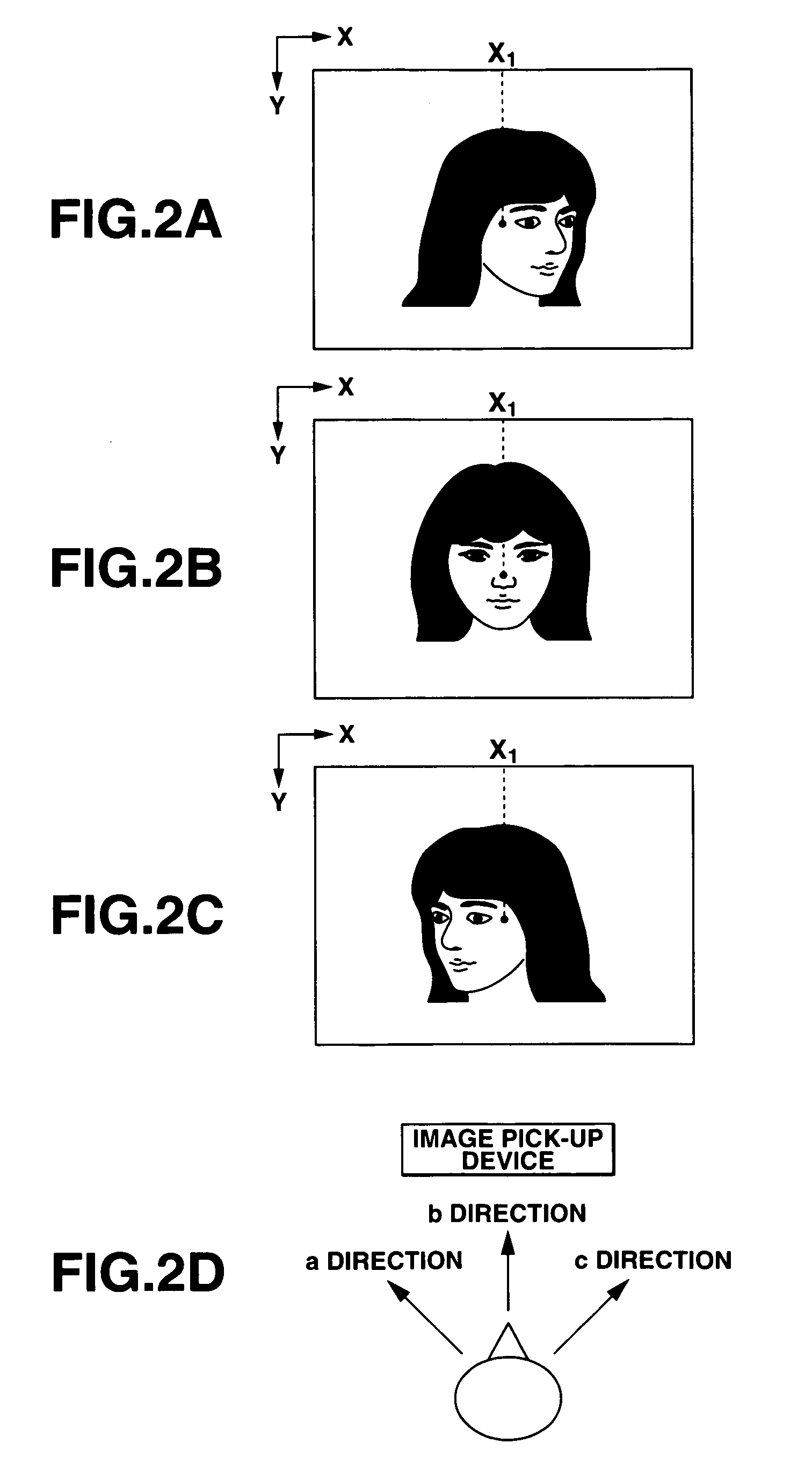
[0074]This is how the angle of orientation of the user's face is detected in the present invention.
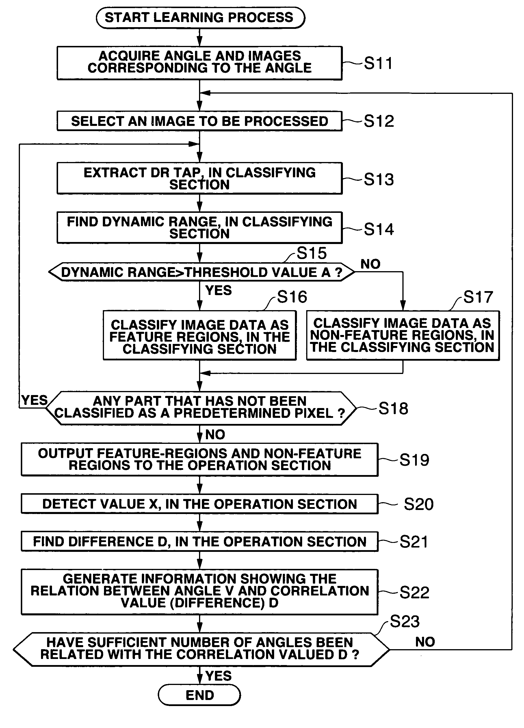
[0075]The pixel values of the eyes (e.g., brown eyes) greatly change, because the sclera (white) and the skin (skin color) surround the eyes. The dynamic range of these pixel values is broad. That is to say, the images of the brown eyes are classified as feature-regions. By contrast, the pixel values of the brown hair do not change so much, and the dynamic range of these pixel values is narrow. Hence, the image of the hair is classified as a non-feature-region. In this manner, dynamic range of DR taps is calculated for the prescribed image region (i.e., 61×61 pixels). The image data is classified in accordance with the dynamic range thus calculated. Therefore, the brown eyes are classified as feature regions, whereas the brown hair is classified as a non-feature region, though the eyes and the hair are of the same color. This makes it possible to detect the orientation of the face base...
second embodiment
[0093]In an image processing apparatus 1 according to the invention, the classifying section 12, operation section 13 and storage section 14 may cooperate to carry out the following process.
[0094]In the second embodiment, the classifying section 12 generates feature-region classified image data from the pre-classification image data supplied from the imaging section 11, in the same way as in the image processing apparatus 1. The classifying section 12 also performs class-number allocation, which will be described later, thereby classifying feature regions into a plurality of classes (i.e., 16 classes, in this embodiment). Further, the classifying section 12 generates a histogram T from the classes of the feature regions. As shown in FIG. 14, the histogram T represents the number of regions (DR taps) of each of the sixteen classes (i.e., classes 0 to 15, in this case), or the frequency of each class.
[0095]The storage section 14 stores reference histograms (three histograms R1, R2 and...
third embodiment
[0125]In an image processing apparatus 1 according to the invention, the classifying section 12, operation section 13 and storage section 14 may cooperate to carry out the following process.
[0126]In the third embodiment, the classifying section 12 generates feature-region classified image data from the pre-classification image data output from the photographing section 11, in the same way as in the image processing apparatus according to the first embodiment. [only three feature regions, for the sake of simplicity.]
[0127]The classifying section 12 then performs class-number allocation on the feature-region classified image data, thereby classifying feature regions of the feature-region classified image data, into a plurality of classes. In this embodiment, the section 12 classifies the feature regions into 16 classes, i.e., the 0th class to the fifteenth class. However, FIG. 22 shows the feature-region classified image data, in which the feature region has been divided into only thr...
PUM
 Abstract
Description
Claims
Application Information
 - R&D
- Intellectual Property
- Life Sciences
- Materials
- Tech Scout
- Unparalleled Data Quality
- Higher Quality Content
- 60% Fewer Hallucinations
Browse by: Latest US Patents, China's latest patents, Technical Efficacy Thesaurus, Application Domain, Technology Topic, Popular Technical Reports.
© 2025 PatSnap. All rights reserved.Legal|Privacy policy|Modern Slavery Act Transparency Statement|Sitemap|About US| Contact US: help@patsnap.com


