
Holder for attaching a remote control to a piece of furniture

a technology for attaching a remote control and a piece of furniture, which is applied in the direction of machine supports, other domestic objects, mechanical apparatus, etc., can solve the problems of more difficult to misplace the enclosure containing more difficult to misplace the remote control unit, and the holder is thus convenient, unobtrusive, and accessible. , to achieve the effect of simple and inexpensive manufacture and simple us

Inactive Publication Date: 2005-11-22
HARE DAVID
View PDF13 Cites 18 Cited by
  • Summary
  • Abstract
  • Description
  • Claims
  • Application Information

AI Technical Summary

Benefits of technology

[0011]Accordingly, an object of the present invention is to provide a holder for attaching a remote control to a piece of furniture that avoids the disadvantages of the prior art.
[0012]Another object of the present invention is to provide a holder for attaching a remote control to a piece of furniture that is simple and inexpensive to manufacture.
[0013]Still another object of the present invention is to provide a holder for attaching a remote control to a piece of furniture that is simple to use.

Problems solved by technology

A third example, U.S. Pat. No. 5,195,634 to Zaug teaches a holder which makes it more difficult to misplace remote control units.
Since the enclosure is larger than the remote control unit, it is more difficult to misplace the enclosure containing the remote control unit than it is to misplace the remote control unit alone.
The holder is thus conveniently, unobtrusively, accessibly, and visibly stored close at hand, without occupying horizontal table space or requiring a separate piece of furniture for secure storage.
Furthermore, even though these innovations may be suitable for the specific individual purposes to which they address, however, they would not be suitable for the purposes of the present invention as heretofore described.

Method used


Image

  • Holder for attaching a remote control to a piece of furniture
  • Holder for attaching a remote control to a piece of furniture

Examples


Embodiment Construction

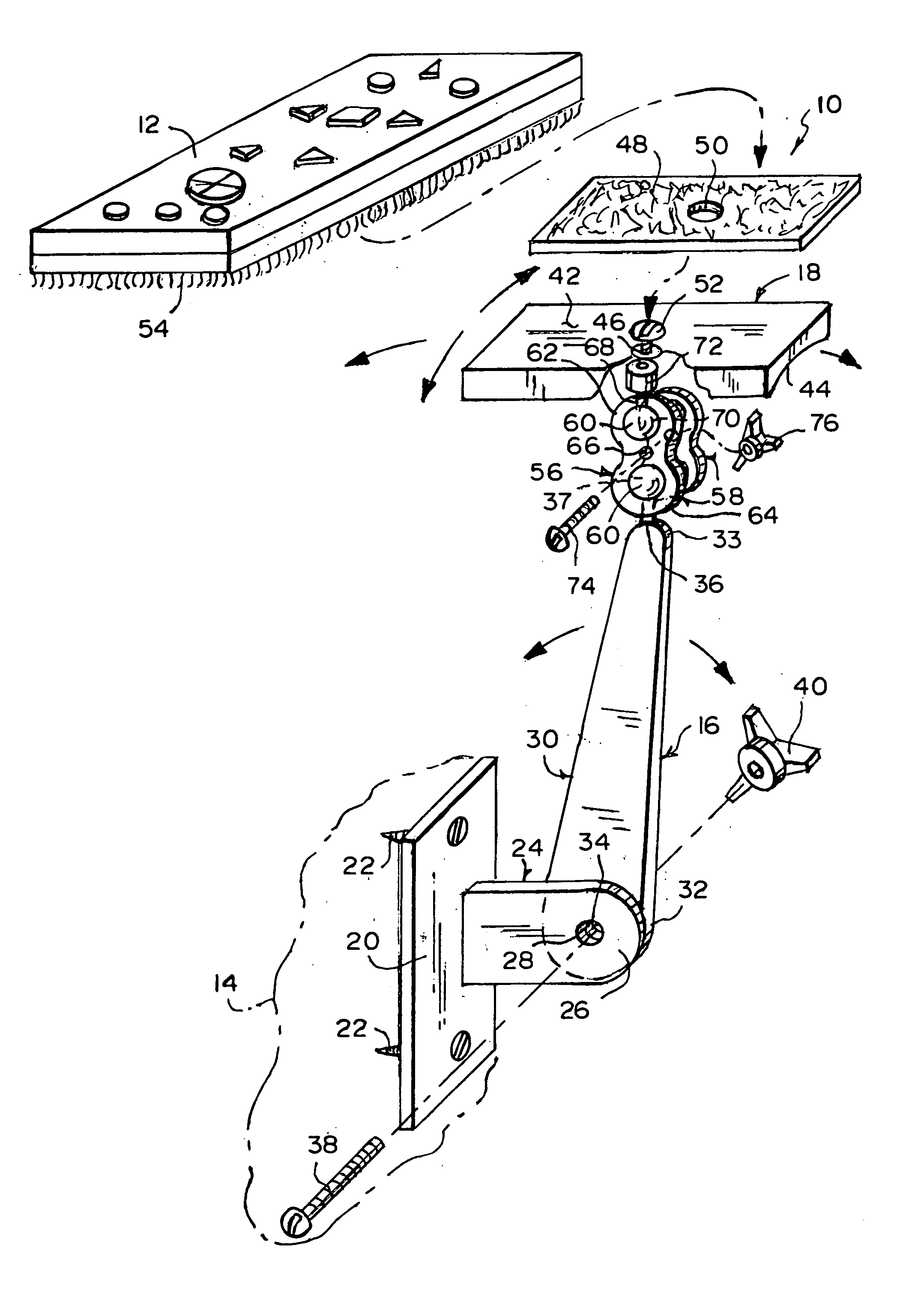
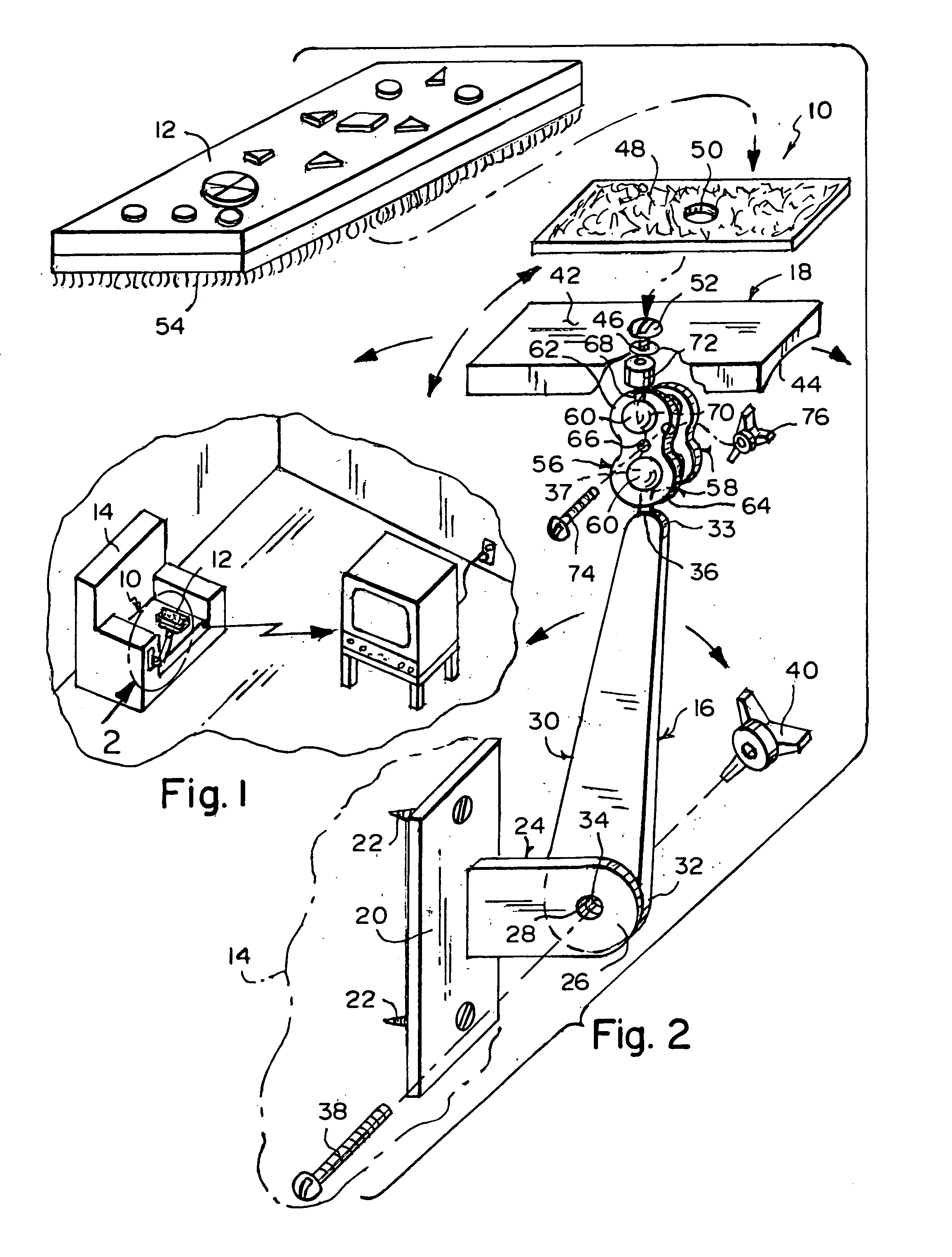
[0055]Referring now to the figures, in which like numerals indicate like parts, and particularly to FIG. 1, the holder of the present invention is shown generally at 10 for attaching a remote control 12 to a piece of furniture 14.

[0056]The configuration of the holder 10 can best be seen in FIG. 2, and as such, will be discussed with reference thereto.

[0057]The holder 10 comprises a bracket 16 and a platform 18. The bracket 16 is for attaching to the piece of furniture 14 and the platform 18 is pivotally attached to the bracket 16 and is for holding the remote control 12.

[0058]The bracket 16 comprises a mounting plate 20 for attaching to the piece of furniture 14 by screws 22.

[0059]The bracket 16 further comprises a stationary arm 24. The stationary arm 24 of the bracket 16 extends outwardly from the mounting plate 20 thereof to a terminal end 26. The terminal end 26 of the stationary arm 24 of the bracket 16 has a through bore 28 that extends laterally therethrough.

[0060]The bracket...


PUM


Abstract

A holder for attaching a remote control to a piece of furniture. A bracket attaches to the piece of furniture and a platform is pivotally attached to the bracket and holds the remote control. The bracket includes a mounting plate, a stationary arm, and a movable arm. The platform has a lowermost surface which is concave allowing the platform to be used with remote controls having either flat or convex lower surfaces by merely inverting the platform accordingly, and a first portion of hook and loop fasteners screwed to the platform. A second portion of hook and loop fasteners is attached to the remote control and releasably engages with the first portion of hook and loop fasteners so as to releasably engage the remote control with the platform. A joint pivotally attaches the platform to the bracket and includes a pair of plates and a post with a second ball bearing and a screw boss.

Description

BACKGROUND OF THE INVENTION[0001]1. Field of the Invention[0002]The present invention relates to a holder for attaching to a piece of furniture. More particularly, the present invention relates to a holder for attaching a remote control to a piece of furniture.[0003]2. Description of the Prior Art[0004]Numerous innovations for remote control holders have been provided in the prior art that will be described. Even though these innovations may be suitable for the specific individual purposes to which they address, however, they differ from the present invention.[0005]A first example, U.S. Pat. No. 4,831,673 to Winckler teaches an apparatus for holding articles to a bed having a mattress, box spring and bed frame and consists of a receptacle member formed to back of a channel shaped clamp member that can be attached to side of the bed frame. The receptacle member has an open top to hold the article therein so that a person can remove the articles from the receptacle member when needed....

Claims


Application Information

Patent Timeline
IPC IPC(8): A47B81/06H03J9/00
CPCA47B81/06H03J9/00
Inventor HARE, DAVID
Owner HARE DAVID
Learn More