Ink container and recording apparatus

a recording apparatus and jet type technology, applied in the field of jet type recording apparatus, can solve the problems of reduced printing capacity, reduced number of prints produced per container, and high exchange frequency of ink containers, so as to improve the position accuracy of ink containers and improve the reliability. the effect of improving the accuracy of the positional accuracy

Inactive Publication Date: 2005-11-22
CANON KK
View PDF29 Cites 34 Cited by
  • Summary
  • Abstract
  • Description
  • Claims
  • Application Information

AI Technical Summary

Benefits of technology

[0016]Accordingly, it is a principal object of the present invention to provide an ink container which is capable of accurately displaces a mechanical ink container detecting means provided in the main assembly of a printer through a predetermined distance.
[0018]With this structure, when the projection is abutted to the ink container detecting means, even if the bottom side is deformed by the reaction force of the sealing member, the projection is not influenced by the reaction force since the projection is disposed adjacent t vertical wall. When the projection is disposed adjacent the engaging portion, the positional accuracy when the ink container is mounted is improved to assure the operation of the ink container detecting means. Since the projection is provided in the recess provided by the stepped portion, so that mechanical strength of the casing is enhanced adjacent the projection, and the positional accuracy when the ink container is mounted, thus assuring the operation of the ink container detecting means.
[0020]This feature is effective to protect, form damage, the projection even if the ink container is inadvertently let fall upon mounting of the ink container to the cartridge, and therefore, the reliability is further improved.
[0022]Thus, the recording apparatus using the ink container of the present invention has holding means provided with ink container detecting means for mechanically detecting mounting of the ink container. The recording apparatus of the present invention does not necessitate electrical storing means in the ink container, the inside capacity of the ink container can be made large correspondingly. In addition, the positional accuracy between the ink container detecting means and the ink container which is necessary when the recording apparatus is downsized, can be improved.
[0023]The recording apparatus of the present invention may include the ink container detecting means provided in the neighborhood of the side wall of the holding means. By disposing the ink container detecting means adjacent the side wall, it is relatively free of influence of deformation, so that positional accuracy between the ink container detecting means and the projection of the ink container can be further improved.

Problems solved by technology

However, with the decrease of the size of the ink container, the inside volume of the container decreases, with the result that ink capacity decreases, and the number of prints producible per container reduces, and therefore, high exchange frequency of the ink container.
However, when an exchangeable ink container is carried on an ink jet cartridge which is detachably mountable to the printer, it is difficult to accomplish a sufficient positional accuracy between the ink container detecting means and the ink container because of mounting errors of the respective elements.

Method used


Image

  • Ink container and recording apparatus
  • Ink container and recording apparatus
  • Ink container and recording apparatus

Examples


first embodiment

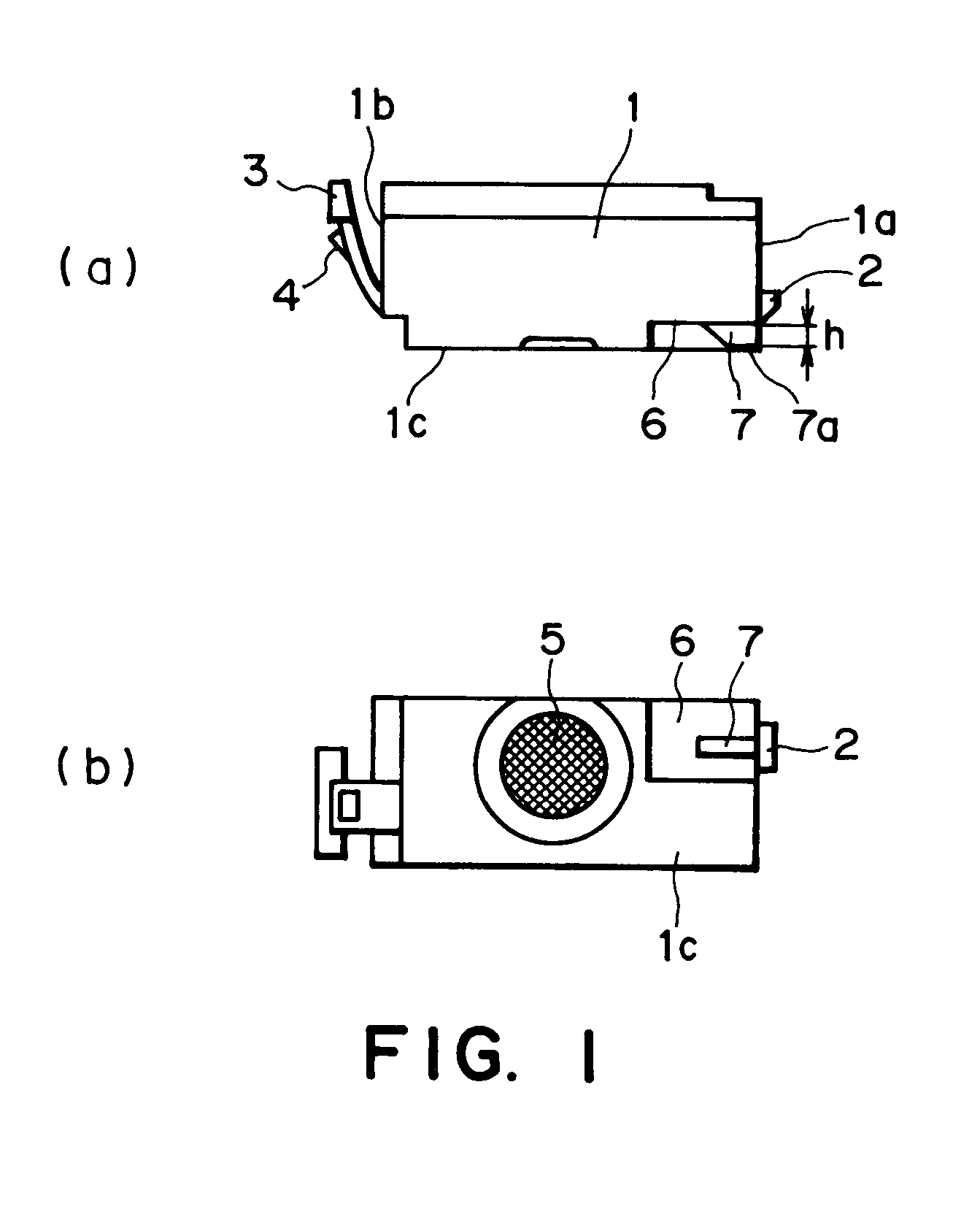
[0033]FIG. 1 is a schematic view of an ink jet cartridge according to a first embodiment of the present invention, wherein (a) is a side view, and (b) is a bottom view.

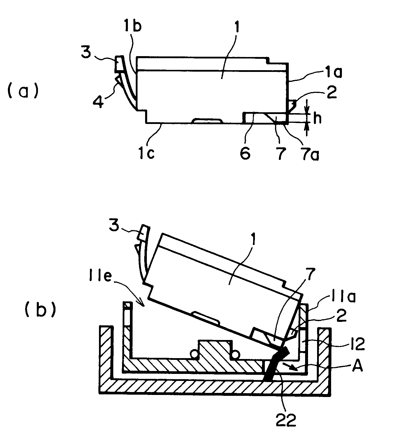
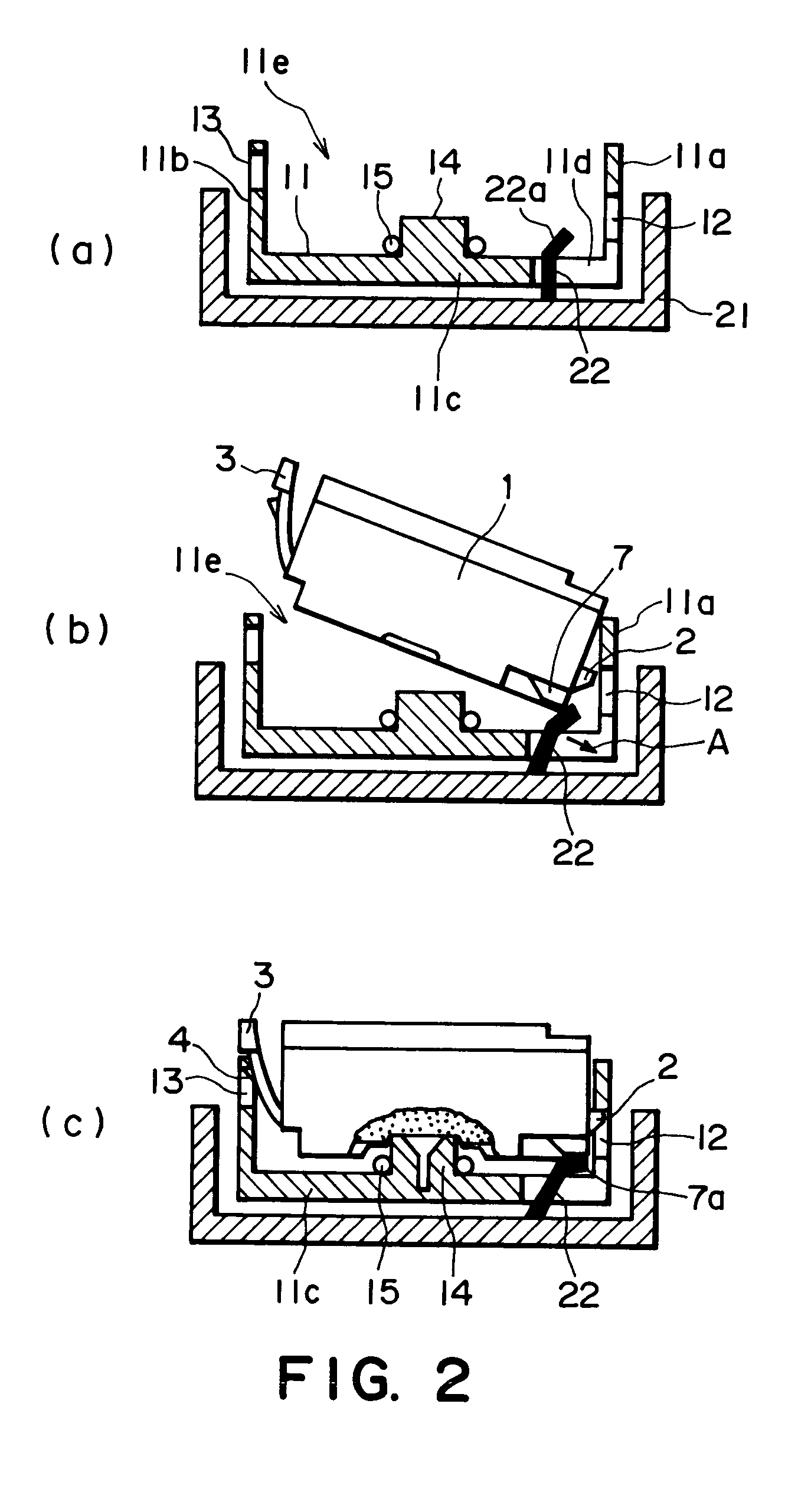
[0034]The ink container 1 accommodating ink therein has, on a first side surface 1a, a retention claw 2 which is a first engaging portion engageable with a retention hole 12 formed in an ink jet cartridge 11 which will be described hereinafter, and has, on a second side surface 1b which is the opposite side, a latch lever 3 having a latch claw 4 which is a second engaging portion. The bottom side 1c of the ink container 1 is provided with an ink supply port 5 for supplying ink to the ink jet cartridge 11. The bottom side 1c has a step 6 of a depth h from the bottom side 1c to form a recess. From the bottom of the recess, a sensor pushing projection 7 is projected, and it is effective to push by an abutment surface 7a an ink container sensor 22 provided in a carriage 21 which will be described hereinafter. The height o...

second embodiment

[0046]FIG. 3 is a schematic view of an ink container according to a second embodiment of the present invention, wherein (a) is a side view, (b) is a bottom view. FIG. 4 is schematic view illustrating process of mounting of an ink container according to the second embodiment of the present invention, wherein (a) shows a state in which the ink container is not mounted; (b) shows a state in which the ink container is in the process of mounting; (c) shows a state in which the mounting manipulation has been completed.

[0047]The ink container 101 of this embodiment is the same as that of the first embodiment in the basis structure, but the inside thereof is divided into three chambers, which contain cyan, magenta, yellow inks, respectively. The chambers are provided with respective ink supply ports 105c, 105m, 105y in the bottom side 101c. In the first embodiment, the step 6 is formed in the bottom side 1c at the first side surface 1a side where the retention claw 2 is provided, and the pr...

third embodiment

[0057]FIG. 5 is a schematic view of an ink container according to a third embodiment of the present invention, wherein (a) is a side view thereof, and (b) illustrates a sensor pushing projection provided on the bottom side of the latch lever 3. The structures of this embodiment are the same as those of second embodiment except that abutment surface relative to the ink container sensor which is a bottom side of the sensor pushing projection, is inclined, and therefore, the same reference numerals as with the second embodiment are assigned to the elements having the corresponding functions, and the detailed descriptions for such elements are omitted for simplicity.

[0058]The sensor pushing projection 207 is inclined by an angle a relative to the step surface 106a of the step 106 parallel with the bottom side 101c of the ink container 101.

[0059]FIG. 6 is a schematic view illustrating a state that sensor pushing projection begins to abut the ink container sensor during the process of ink...


PUM


Abstract

An ink container detachably mountable to an ink jet recording apparatus which includes a cartridge provided with a recording head and capable of detachably carrying the ink container, and includes a mechanical switch for detecting mounting of the cartridge by its displacement, the container including a bottom side which is provided with an ink supply port for supplying the ink from an inside of the container to the recording head and which takes a bottom position in use; a substantially vertical side having an engaging portion for mounting the ink container to the cartridge; a stepped portion, in the bottom side, forming a recess having an end which is open at the vertical side; and a projected abutment portion, provided adjacent the vertical side in the recess, for displacing the mechanical switch.

Description

FIELD OF THE INVENTION AND RELATED ART[0001]The present invention relates to an ink jet type recording apparatus and an ink container therefor wherein ink is ejected to effect recording on a recording material, more particularly to a presence-absence detection of the ink container detachably mountable to the recording apparatus.[0002]There are known various types of recording apparatuses for effecting printing on a sheet of paper, textile, a plastic resin material sheet, OHP sheet or the like (hereinafter simply called “recording material”), for example, a wire dot type, a thermosensitive type, a thermal transfer type, ink jet type, wherein recording heads are provided.[0003]Among them, ink jet recording apparatus is advantageous in that running cost is low, that apparatus size is small and that color image recording is easy. Among the ink jet apparatus, a line type apparatus wherein the use is made with a line type recording head having a great number of ejection outlets are arrang...

Claims


Application Information

Patent Timeline
Patent Type & Authority Patents(United States)
IPC IPC(8): B41J2/175B41J2/17B41J2/14B41J27/00B41J29/393
CPCB41J2/1752B41J2/17
Inventor MATSUO, KEISUKEKOTAKI, YASUOOHASHI, TETSUYASATO, NORIKOHAYASHI, HIROKI
Owner CANON KK
Why Eureka
Try Eureka