Safety device for an injection syringe

a safety device and syringe technology, applied in the direction of intravenous devices, infusion devices, injection needles, etc., can solve the problems of contaminating, touching or pricking people, and syringes that are dangerous, so as to avoid the effect of such accidents

Inactive Publication Date: 2005-11-22
NEMERA LA VERPILLIERE SAS
View PDF7 Cites 52 Cited by
  • Summary
  • Abstract
  • Description
  • Claims
  • Application Information

AI Technical Summary

Benefits of technology

[0008]In this safe position, which the needle body reaches only after injection has ended, all risk of accidental injury by contact with the dirty needle is avoided since the needle is retracted inside the sheath and is no longer accessible.
[0010]In other words, the user does not need to compress the spring when engaging the syringe body in the sheath.
[0012]The lack of any need to provide force for compressing the spring at the time the syringe body is inserted also makes it possible to automate assembly of prefilled syringe bodies in safety devices of the invention.

Problems solved by technology

It is also known that syringes constitute instruments that are dangerous, in particular for medical personnel, because after use, their dirty and potentially contaminated needles can accidentally touch or prick people and contaminate them.

Method used


Image

  • Safety device for an injection syringe
  • Safety device for an injection syringe
  • Safety device for an injection syringe

Examples


Embodiment Construction

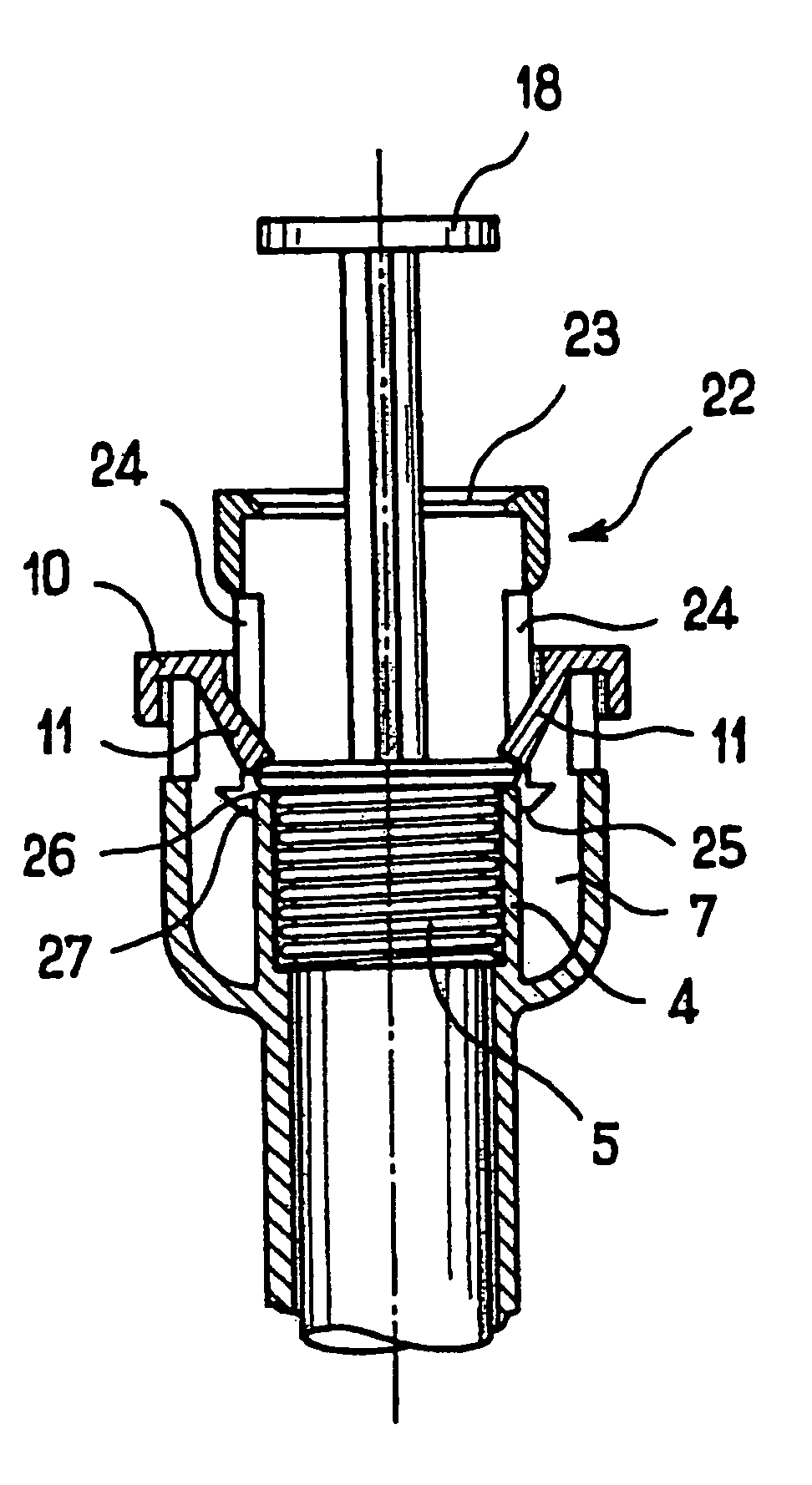
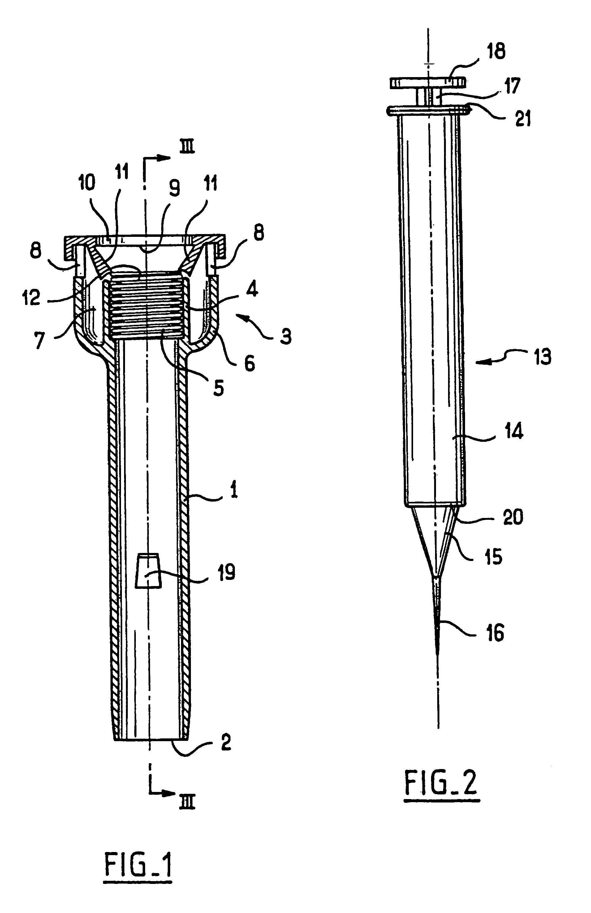
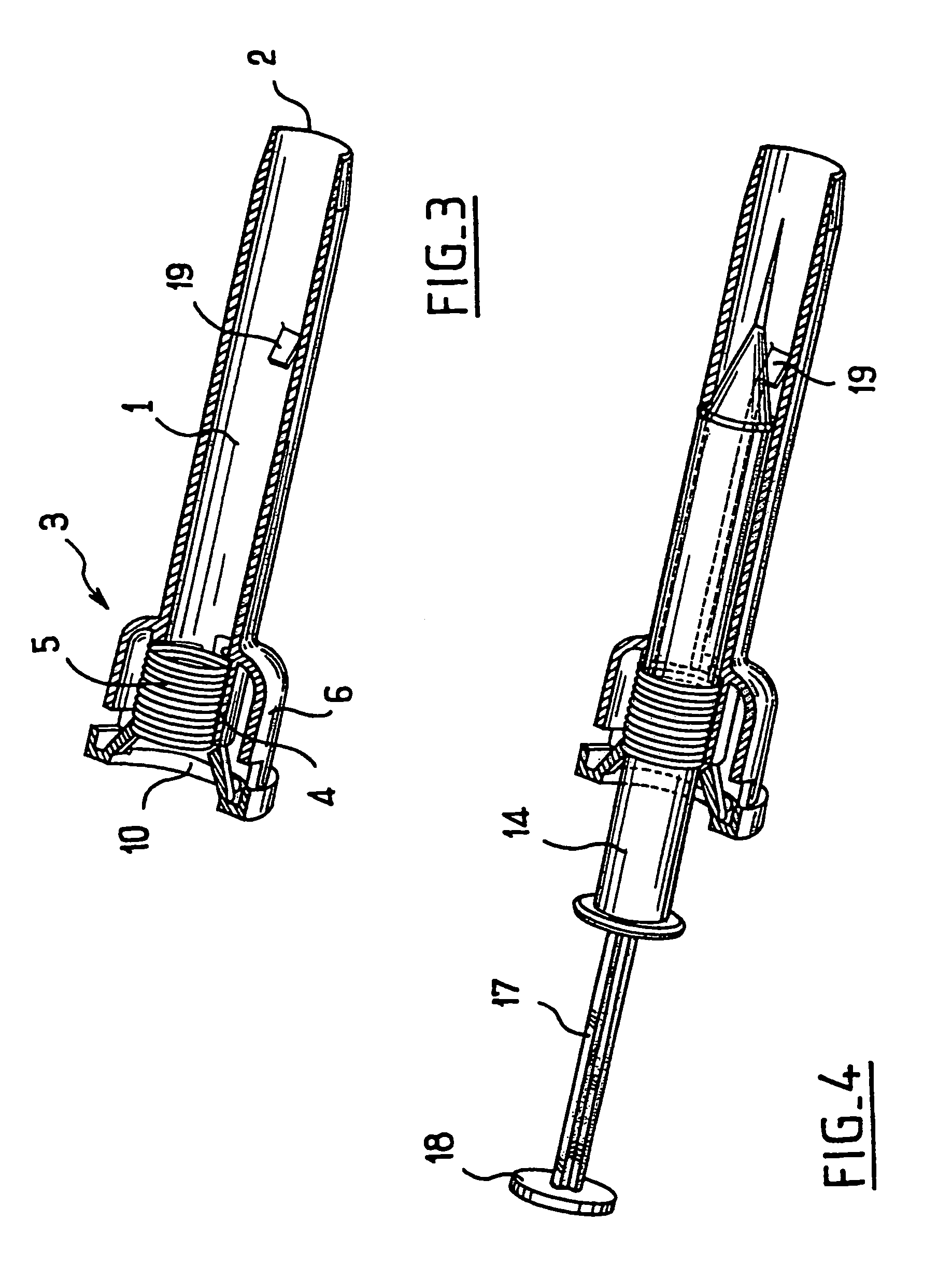
[0031]The sheath of the safety device shown in FIG. 1 comprises a cylindrical portion 1 having a bottom opening 2 and at its end opposite from said opening 2, a head 3 constituted both by a tubular portion 4 which contains a helical spring 5 extending the inside cavity of the cylindrical portion 1 and by an outer wall 6 running parallel with the tubular portion 4 and defining an annular chamber 7 about it.

[0032]The wall 6 has two diagrammatically opposite notches 8 formed in its top edge 9.

[0033]The edge 9 is covered by a ring 10 which is snap-fastened or stuck or bonded to the head. The ring 10 is made separately for ease of manufacture, but it could be obtained integrally with the sheath.

[0034]The ring 10 supports two deformable tabs 11 extending from the vicinity of the edge 9 towards the top edge 12 of the tubular portion 4.

[0035]The bottom ends of the tabs 11 are concave so as to act as abutments for the helical spring 5 which is received in the tubular portion 4 and which has ...


PUM


Abstract

A safety device for a syringe constituted by a body, a needle carrier mounted at one end of the body, a piston that is axially movable in the body, and a piston plunger projecting from the body at its end opposite from the needle carrier and suitable for pushing the piston inside the body towards the needle carrier, the device comprising a sheath in which the syringe body can slide axially between an injection position in which the needle carrier is flush with one end of the sheath and a safe position in which the needle carrier is retracted into the sheath, a helical spring which is axially compressed when the syringe body is in the injection position, said spring then exerting on said body a force tending to cause it to slide into the safe position, retention means for retaining the syringe body in the injection position, and a release mechanism for releasing the retention means acting on said retention means when the piston plunger of the syringe has pushed the piston inside the body into the vicinity of the needle carrier, wherein the retention means for retaining the body of the syringe in the injection position in the sheath are constituted by at least one radially-movable resilient tab extending substantially longitudinally relative to the sheath and arranged to hold the spring in the compressed state even when the syringe body is not in the sheath.

Description

[0001]The present invention relates to a safety device for an injection syringe.BACKGROUND OF THE INVENTION[0002]It is known that certain injectable medicines are distributed as doses in syringe bodies that are filled in advance, and to which it suffices merely to add piston plungers and needles in order to transform them into syringes.[0003]It is also known that syringes constitute instruments that are dangerous, in particular for medical personnel, because after use, their dirty and potentially contaminated needles can accidentally touch or prick people and contaminate them.OBJECTS AND SUMMARY OF THE INVENTION[0004]The present invention seeks to provide a safety device to avoid that kind of accident happening.[0005]The present invention provides a safety device for a syringe constituted by a body, a needle carrier mounted at one end of the body, a piston that is axially movable in the body, and a piston plunger projecting from the body at its end opposite from the needle carrier a...

Claims


Application Information

Patent Timeline
Patent Type & Authority Patents(United States)
IPC IPC(8): A61M5/32
CPCA61M5/326A61M2005/3261
Inventor POUGET, MICHELBONACCI, FABRICE
Owner NEMERA LA VERPILLIERE SAS
Why Eureka
Try Eureka