Air aspirator-mixer

a technology of air aspirator and mixer, which is applied in the direction of liquid degasification, separation process, biological water/sewage treatment, etc., can solve the problems of reducing the scope of application of the device, not being easily replaced, and not being able to prevent the plugging of suspended solids

Inactive Publication Date: 2005-11-29
KORZENIOWSKI JAN A
View PDF13 Cites 36 Cited by
  • Summary
  • Abstract
  • Description
  • Claims
  • Application Information

AI Technical Summary

Benefits of technology

[0006]The air-aspirator-mixer is a device containing a venturi nozzle, an air inlet chamber, a carrier fluid inlet and a fluid / air mixture outlet. The venturi nozzle and the air inlet chamber of the air-aspirator-mixer may be combined with the carrier fluid inlet and the air / fluid mixture outlet which can be used in alternative arrangements to suit the device application, thus rendering flexibility and adaptability to different operating conditions and performance criteria as shown on FIGS. 1, 2&3.

Problems solved by technology

They are predominantly applicable to treatment systems for water and industrial wastewater, but not to sanitary sewage and industrial wastewaters containing relatively large sized suspended solids.
The devices lack the ability of preventing plugging by suspended solids and removal of suspended solids which accumulate in the devices.
The devices typically employ a built-in venturi throat of fixed dimension or size which reduces its scope of application, and can not be readily replaced when worn out.
The efficiency of prior art gas or liquid aspiration and mixing with a carrier fluid is low, which results in high energy consumption and initial costs.

Method used


Image

  • Air aspirator-mixer
  • Air aspirator-mixer
  • Air aspirator-mixer

Examples


first embodiment

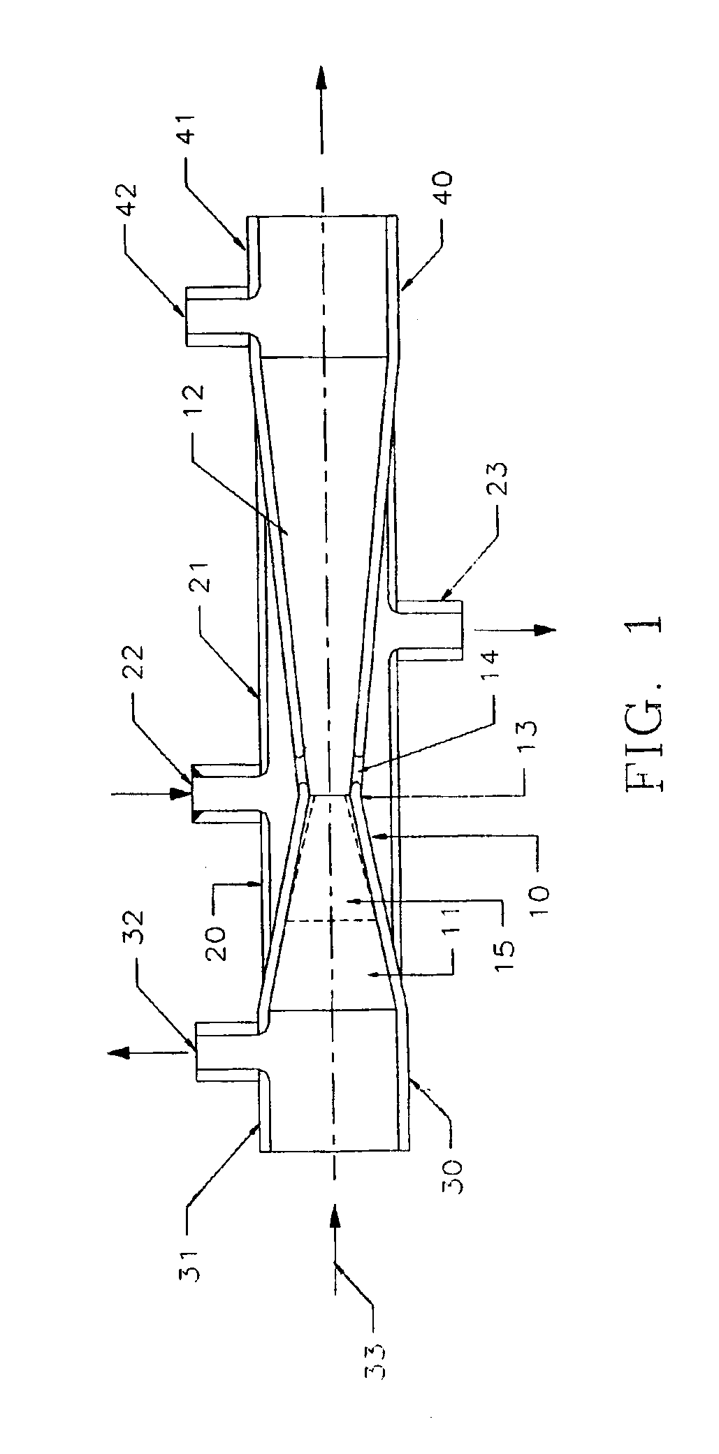
[0015]the invention is shown on FIG. 1. A venturi nozzle, generally indicated by the reference numeral 10, has a constricting inlet portion 11 and an expanding outlet portion 12, both of which are conically shaped and are connected together by a generally short throat 13. An optional removable inlet constricting liner 15 may be inserted within the inlet portion 11. The liner is provided to obtain a different size of opening at the throat 13 without changing the entire venturi nozzle. The liner also reduces or eliminates wear in the throat area, as discussed later.

[0016]The expanding outlet portion 12 consists of a number of circumferentially spaced air inlet apertures 14 which preferably are circular or of another regular shape with rounded edges. The apertures are of adequate size to minimize the inlet air or liquid head losses, are generally evenly spaced about the periphery of the expanding outlet portion 12, and are located close to the throat 13 of the venturi.

[0017]An air inle...

second embodiment

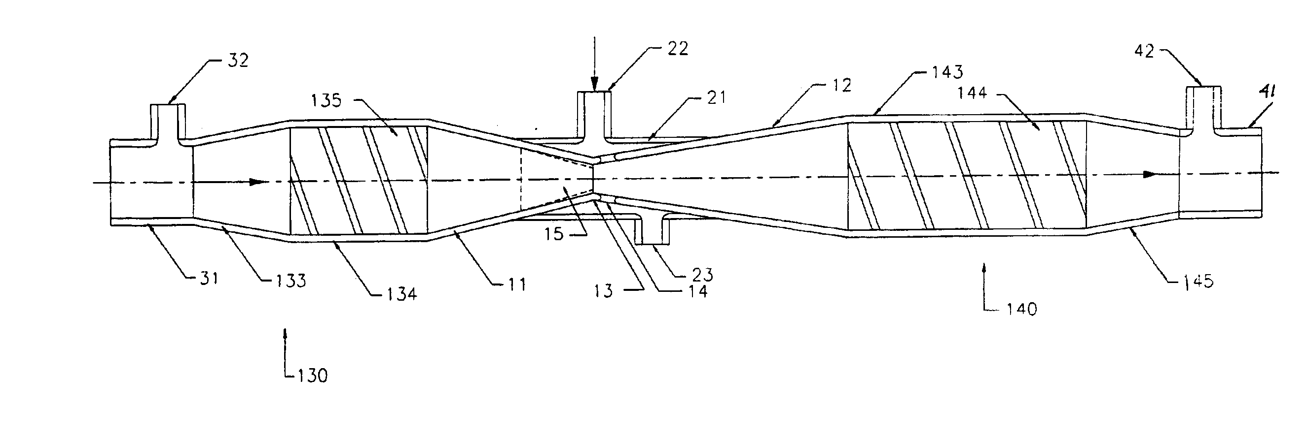
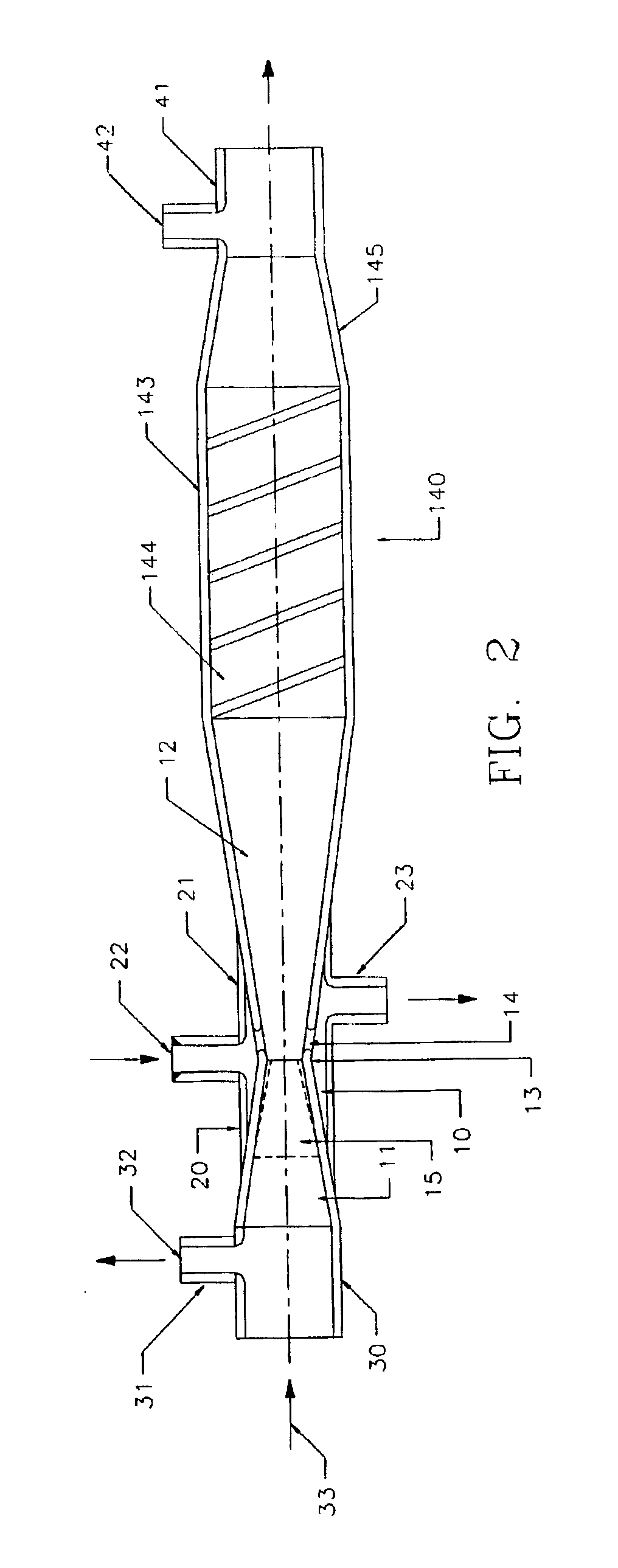
[0020]the invention is shown in FIG. 2. For the various embodiments disclosed herein, the same reference numerals are used for the same or substantially similar features. Hence, the venturi nozzle 10, air inlet chamber 20, and the carrier fluid inlet 30 are in essence the same as those shown and described in the FIG. 1 embodiment. However in this embodiment, the fluid / air mixture outlet 140 incorporates a longitudinally extended cylindrical section 143 adjacent the downstream end of the venturi's outlet portion 12. The cylindrical section 143 is of a larger diameter than the outlet portion 41, and contains a spiral mixer 144 for additional mixing of air or fluid with the carrier fluid. A conically shaped constricting portion 145 is located intermediate the cylindrical section 143 and the smaller cylindrical outlet portion 41, which also has an optional radial port 42 for instrument or flushing connection.

[0021]In a third embodiment of the invention is shown on FIG. 3, the carrier fl...


PUM

PropertyMeasurementUnit
diameteraaaaaaaaaa
sizeaaaaaaaaaa
energyaaaaaaaaaa

Abstract

A single port venturi device is provided for aeration of wastewaters containing suspended solids. The device has a non-obstructive design which prevents attachment or accumulation of suspended solids, and promotes even air distribution for efficient aspiration of air and mixing of air and wastewater. The device has provisions for adjustment of the venturi throat size, for protection of the throat from wearing out, for enhancing air and wastewater mixing capabilities, and for flushing of the solids accumulated in the air entrance.

Description

FIELD OF THE INVENTION[0001]This invention relates to a process for air aspiration and mixing with fluid in a closed conduit, in particular with the use of a venturi means.BACKGROUND OF THE INVENTION[0002]A variety of gas / fluid or fluid / fluid mixing devices have been devised wherein a venturi is employed with different types of air or fluid injectors and mixers. The prior art devices are predominantly applicable to small fluid flows containing suspended solids of a relatively small size or no suspended solids at all. The devices can mix a fluid with another fluid, or a gas (typically air) with a fluid. They are predominantly applicable to treatment systems for water and industrial wastewater, but not to sanitary sewage and industrial wastewaters containing relatively large sized suspended solids. The devices lack the ability of preventing plugging by suspended solids and removal of suspended solids which accumulate in the devices. The devices typically employ a built-in venturi thro...

Claims


Application Information

Patent Timeline
Patent Type & Authority Patents(United States)
IPC IPC(8): B01F25/70C02F1/74C02F3/12
CPCB01F3/0446B01F5/0413B01F5/0415B01F5/0428C02F3/1294C02F1/74Y10S261/56B01F23/232B01F25/3121B01F25/31242B01F25/312Y02W10/10B01F23/2326
Inventor KORZENIOWSKI, JAN A.
Owner KORZENIOWSKI JAN A
Why Eureka
Try Eureka