
Vehicular door

a technology for vehicles and doors, applied in the field of doors, can solve the problems of increasing the number of man-hours in the assembling process of vehicles, the weight of doors and the cost, and the increase of the number of parts, so as to prevent the prior drawbacks

Inactive Publication Date: 2005-11-29
AISIN SEIKI KK
View PDF18 Cites 84 Cited by
  • Summary
  • Abstract
  • Description
  • Claims
  • Application Information

AI Technical Summary

Benefits of technology

The present invention provides a vehicular door that solves previous drawbacks. The door has an outer panel and an inner panel with window portions, a space between the lower side region of the outer panel and the lower side region of the inner panel where a window glass for opening and closing the window portions is placed, and a module mounting opening on the lower side region of the inner panel. The module structure is mounted on the inner panel and includes a remote control mechanism and a latch mechanism for maintaining the door in closing state by engaging it with the body of the vehicle. The module base is fixed to the module mounting opening at its peripheral portion. The technical effect of this invention is to provide a door that has improved functionality and design.

Problems solved by technology

In the prior sliding door for a vehicle, as mentioned above, since a great number of functional components are mounted on the inner panel through brackets, the number of man-hour in assembling process of a vehicle and the number of part increase and the weight of the door and the cost increase.
Further, since a moving up and down actuator 8 of the window regulator 7 is mounted at the outside of the inner panel, the waterproofing becomes insufficient and there was a case that the insufficient waterproofing causes a malfunction of the moving up and down actuator 8 which is an electrical part.

Method used


Image

  • Vehicular door
  • Vehicular door
  • Vehicular door

Examples


Embodiment Construction

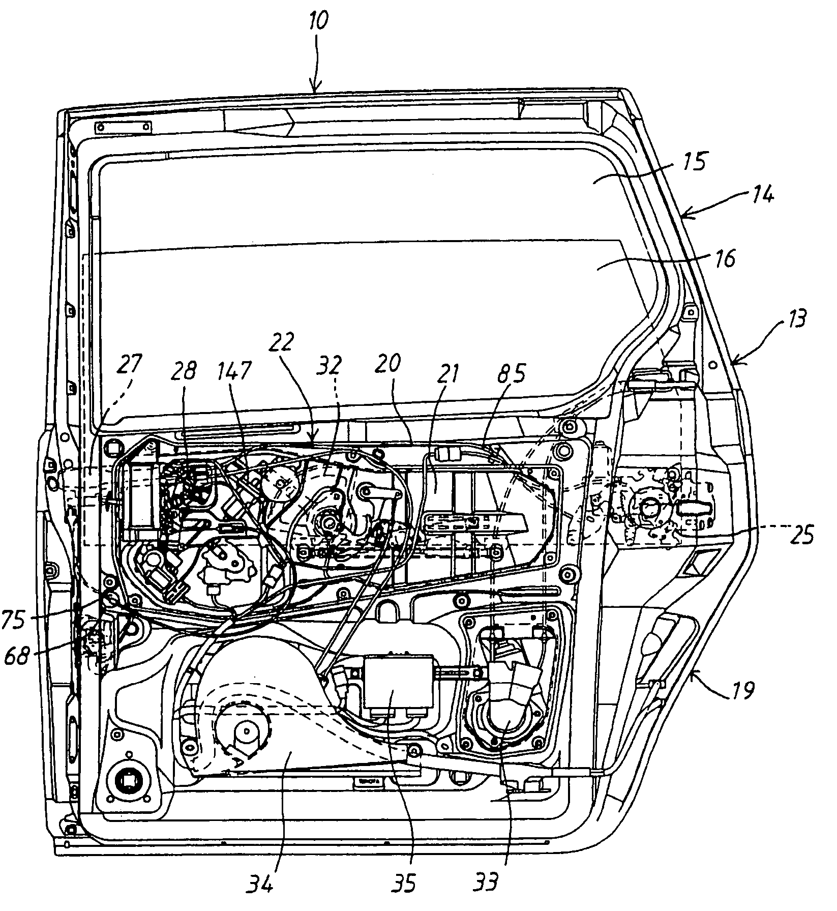
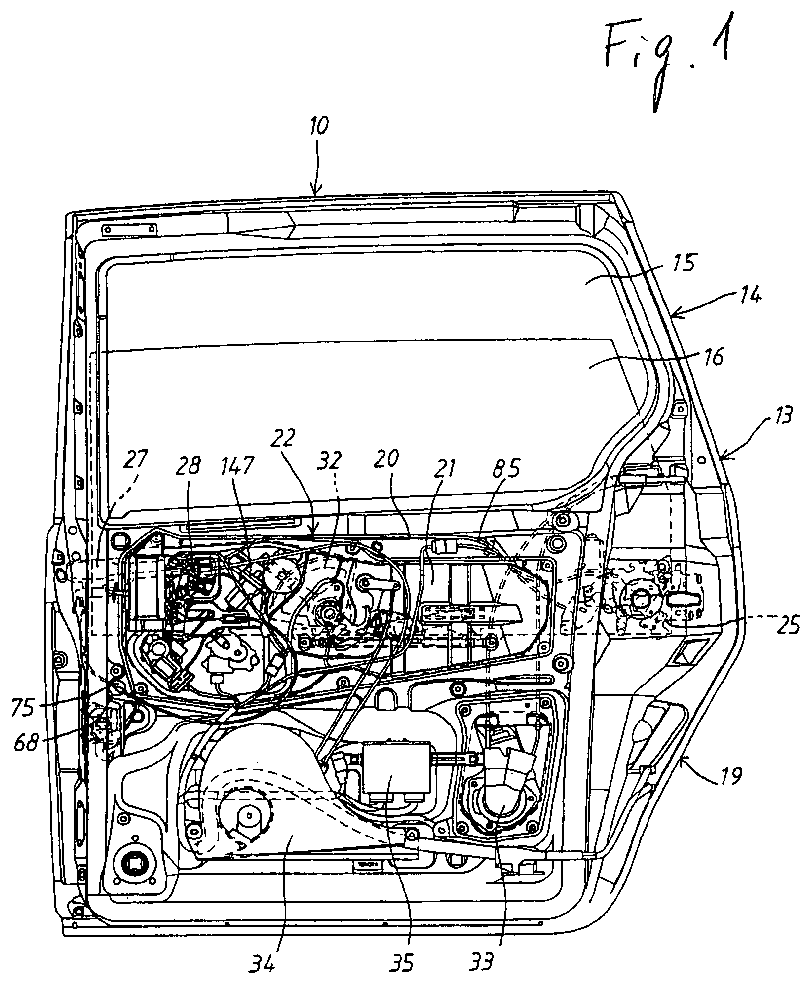
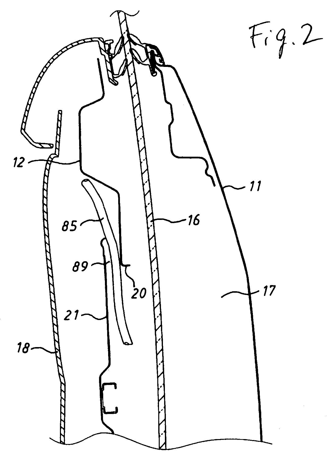
[0027]Hereinafter, a preferred embodiment of the present invention will be explained referring to drawings. FIG. 1 is a front view of a sliding type door 10 for a motor vehicle in which a trim is removed according to the present invention. FIG. 2 is a partial sectional side view of the sliding door 10 for a motor vehicle. FIG. 3 is a front view of a module structure 22 in which a plurality of functional components are mounted to a module base 21. As shown in FIG. 1 to FIG. 3, a window portion 15 penetrates an upper side region 14 of a door main body 13 which is formed by connecting between an outer panel 11 and an inner panel 12 at their peripheral portions and is provided. In a lower side region 19, a space 17 in which a window glass 16 for opening and closing the window portion 15 is disposed so as to be able to move up and down is formed between the outer panel 11 and the inner panel 12. The numeral 18 is a trim which is mounted at the inside of a compartment of the door main bod...


PUM


Abstract

A door for a motor vehicle includes an outer panel and an inner panel in which window portions are formed at their upper side region and which are connected at their peripheral portions, a space which is formed between the lower side region of the outer panel and the lower side region of the inner panel and in which a window glass for opening and closing the window portions is disposed so as to be able to move up and down, a module mounting opening formed on the lower side region of the inner panel and a module structure constituted by mounting a plural functional components to a module base, wherein the module base is fluid-tightly fixed to the module mounting opening at its peripheral portion and the module structure is mounted on the inner panel.

Description

[0001]This is a continuation of application Ser. No. 10 / 442,270, filed May 21, 2003, now abandoned which is a continuation of application Ser. No. 10 / 253,533, filed Sep. 25, 2002, now abandoned which is incorporated herein by reference.BACKGROUND OF THE INVENTION[0002]1. Field of the Invention[0003]The present invention relates to a door for a motor vehicle.[0004]2. Description of the Related Art[0005]As a conventional door for a motor vehicle, particularly a conventional sliding door for a motor vehicle, a door stated in “Estima T / L Service manual” issued on January 2000 by TOYOTA MOTOR CORPORATION is known. As shown in FIG. 16 and FIG. 17, in this door, an outer panel having a window portion formed at its upper side region and an inner panel having a window portion formed at its upper side portion are opposed and are connected at their peripheral portions and a space is formed between the lower side region of the outer panel and the lower side region of the inner panel and a windo...

Claims


Application Information

Patent Timeline
Patent Type & Authority Patents(United States)
IPC IPC(8): E05B83/36B60J1/17B60J5/04E05B77/34E05B79/04E05B79/22E05B83/40
CPCB60J5/0416E05Y2201/434E05Y2600/41E05Y2600/46
Inventor FUKUMOTO, RYOICHIYAMADA, KATSUHISAUCHITSUNEMI, MASAYUKIKOBASHI, KENJIOKADA, SHINJIMARUYAMA, KATSUAKI
Owner AISIN SEIKI KK
Learn More