Ink-jet head

a technology of inkjet and pressure chamber, which is applied in the direction of printing and inking apparatus, etc., can solve the problems of variable ink ejecting characteristics of pressure chambers, and achieve the effect of the same ink ejecting characteristics

Inactive Publication Date: 2005-11-29
BROTHER KOGYO KK
View PDF11 Cites 30 Cited by
  • Summary
  • Abstract
  • Description
  • Claims
  • Application Information

AI Technical Summary

Benefits of technology

[0011]According to the present invention, in case that a group of pressure chambers, (group of cavity recesses or group of cavity holes) is formed by a plurality of pressure chambers being arranged in a matrix, the pressure chambers disposed at an outermost periphery of the group of pressure chambers and the pressure chambers disposed at portions other than the outermost periphery of the group of pressure chambers are prevented from being largely different from each other in their shapes due to a flowed-in adhesive, and further, there is not caused so much difference from each other in a bending amount of sidewalls of pressure chambers during ink ejection. Accordingly, it becomes possible to obtain almost the same ink ejecting characteristics both in the pressure chambers disposed at the outermost periphery of the group of pressure chambers and in the pressure chambers disposed at portions other than the outermost periphery of the group of pressure chambers.

Problems solved by technology

Also in this case, similarly to the above-described ink-jet head in which the pressure chambers are arranged in the in-line shape, there may be caused a problem that ink ejecting characteristics of the pressure chambers vary depending on three-dimensional structures surrounding the respective pressure chambers, which differ from each other due to positions in a group of pressure chambers in which a plurality of pressure chambers are arranged in a matrix.

Method used


Image

  • Ink-jet head
  • Ink-jet head
  • Ink-jet head

Examples


Embodiment Construction

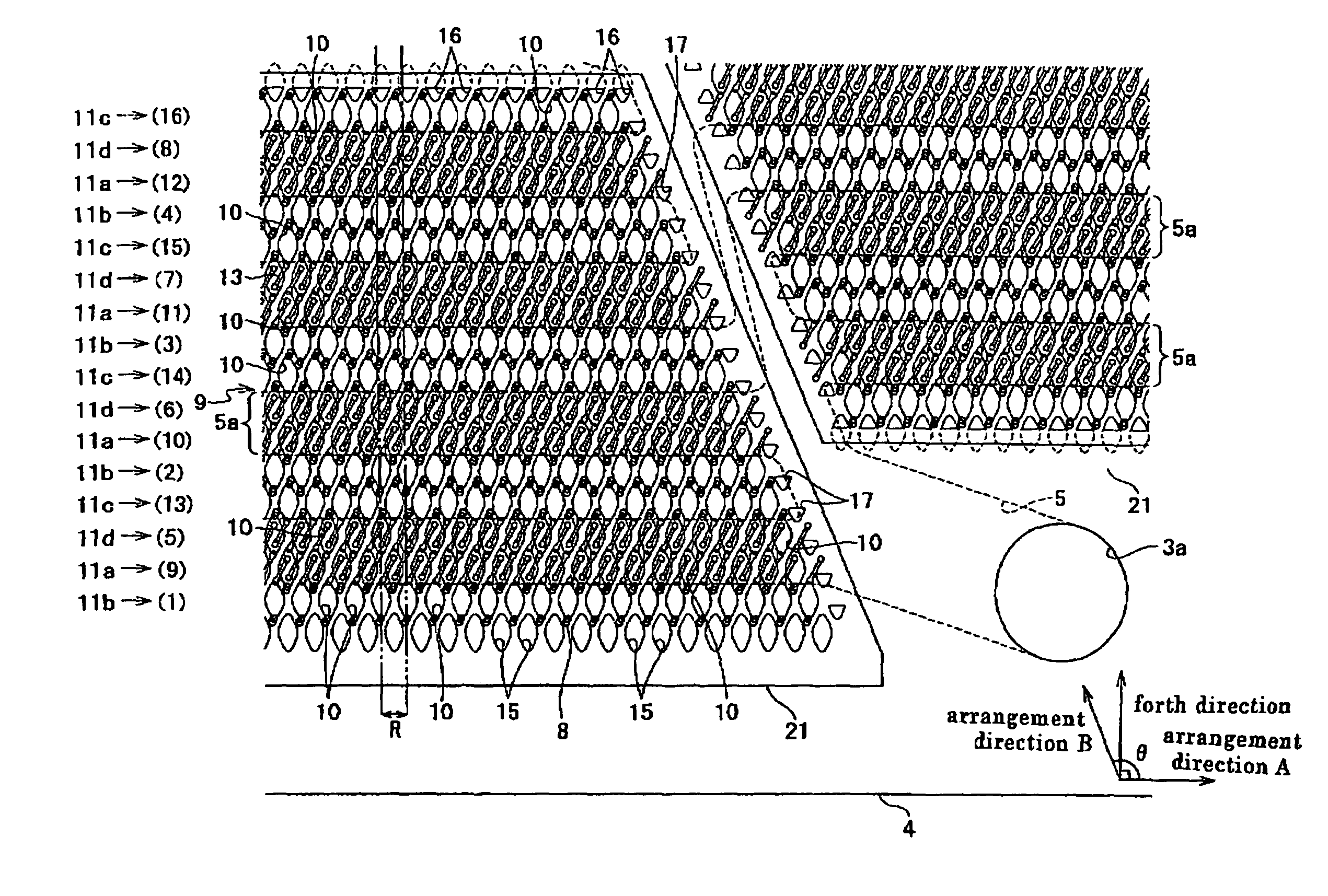
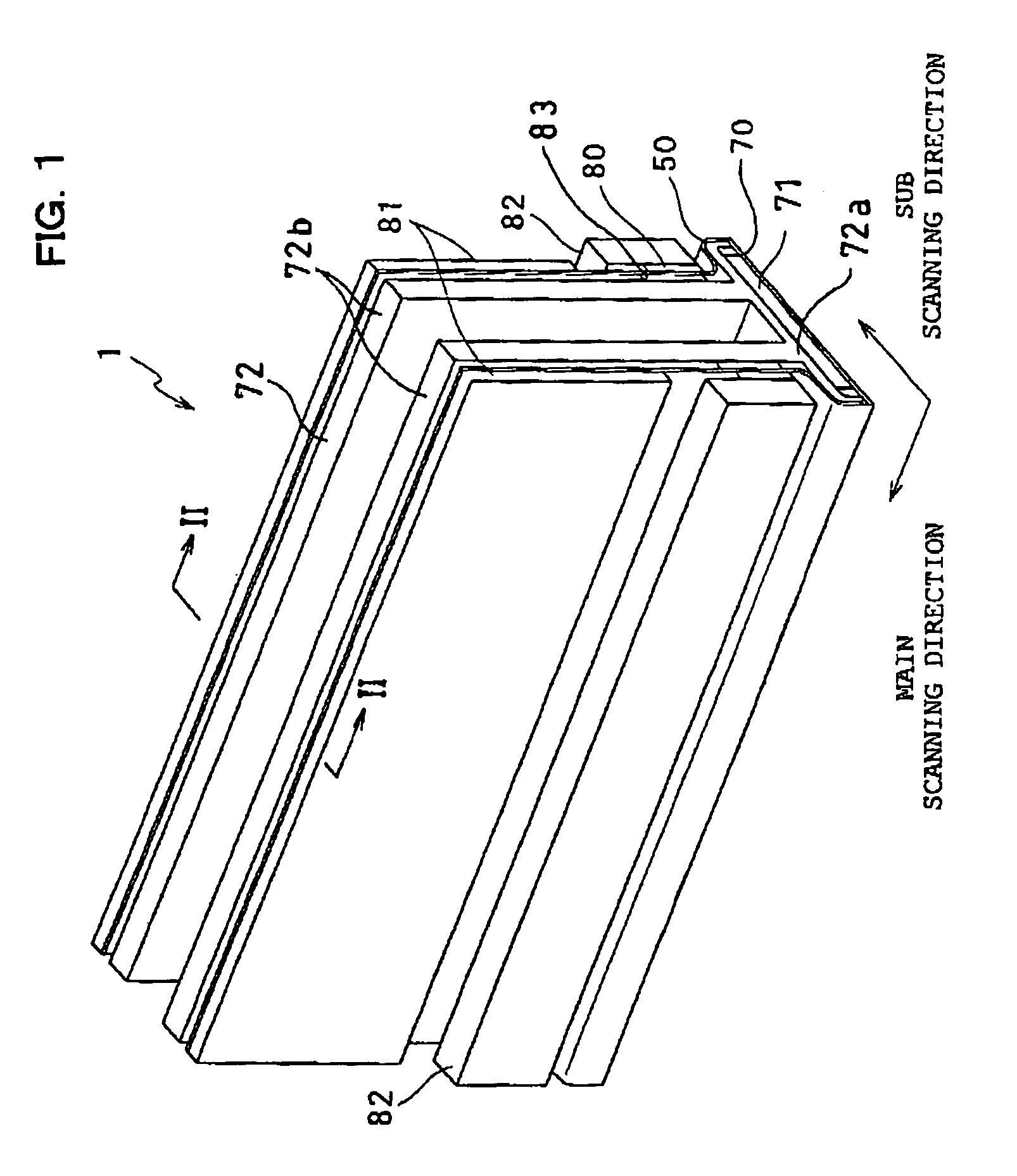
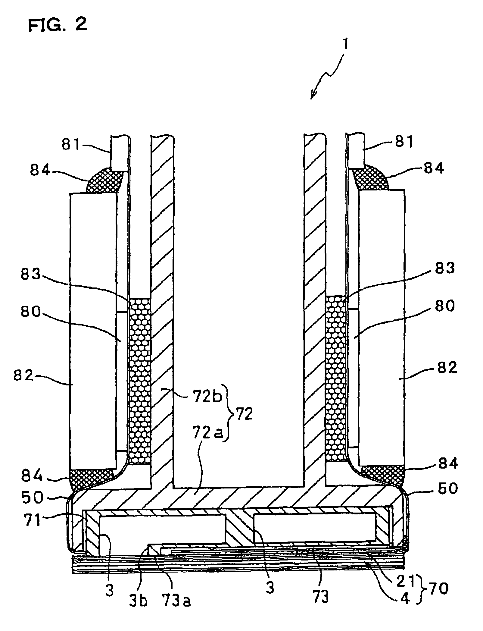
[0024]An ink-jet head according to a first embodiment of the invention will hereinafter be described. FIG. 1 is a perspective view of an ink-jet head 1 according to this embodiment. FIG. 2 is a sectional view taken along line II—II of FIG. 1. The ink-jet head 1 includes a head main body 70 ejecting ink onto a paper and having a rectangular shape in a plan view extending in the main scanning direction, and a base block 71 disposed above the head main body 70 and formed therein with two ink reservoirs 3 that serve as passages for ink supplied to the head main body 70.

[0025]The head main body 70 includes a passage unit 4 formed with ink passages, and a plurality of actuator units 21 bonded to an upper face of the passage unit 4. Both the passage unit 4 and the actuator units 21 are formed of a plurality of thin plates being laminated and bonded to each other. A flexible printed circuit (FPC) 50 as a power supply member is bonded on an upper face of the actuator unit 21, and the FPC is ...


PUM


Abstract

An ink-jet head comprises a passage unit with pressure chambers formed therein, and actuator units for changing the volume of each pressure chamber. In the passage unit, a plurality of cavity recesses each communicating with both a nozzle for ejecting ink and a common ink chamber and each constituting a cavity of the pressure chamber are arranged in a matrix. Further in the passage unit, formed are a plurality of peripheral recesses arranged along a whole periphery of the cavity recesses. The actuator unit closes openings of the cavity recesses to define a plurality of pressure chambers with the passage unit, and changes the volume of each pressure chamber.

Description

BACKGROUND OF THE INVENTION[0001]1. Field of the Invention[0002]The invention relates to an ink-jet head, and particularly to an ink-jet head in which a plurality of pressure chambers are arranged in a matrix to neighbor each other.[0003]2. Description of Related Art[0004]There is known a type of ink-jet head in which ink is ejected through a nozzle communicating with each pressure chamber when pressure is applied by a piezoelectric element to the ink in each of the pressure chambers arranged in one or two rows in an in-line shape. The ink-jet head is manufactured by laminating a plurality of plates. Generally, the pressure chambers are formed by a single plate having holes being sandwiched from both faces thereof by other plates, respectively.[0005]Accordingly, in case of bonding a plurality of plates constituting the pressure chambers to each other with an adhesive, the adhesive applied to interfaces of the plates flows into the holes during a manufacturing process of the ink-jet ...

Claims


Application Information

Patent Timeline
Patent Type & Authority Patents(United States)
IPC IPC(8): B41J2/04B41J2/045B41J2/14
CPCB41J2/14209B41J2002/14217B41J2002/14225B41J2002/14306B41J2002/14459B41J2202/20
Inventor TAIRA, HIROSHI
Owner BROTHER KOGYO KK
Why Eureka
Try Eureka