
Method and apparatus for producing laminated articles

a technology of laminated articles and methods, applied in the direction of layered products, chemistry apparatus and processes, bandages, etc., can solve the problems of oriented processes that may require expensive post-extrusion equipment, and the gathering of elastic components

Inactive Publication Date: 2005-11-29
KIMBERLY-CLARK WORLDWIDE INC
View PDF338 Cites 96 Cited by
  • Summary
  • Abstract
  • Description
  • Claims
  • Application Information

AI Technical Summary

Benefits of technology

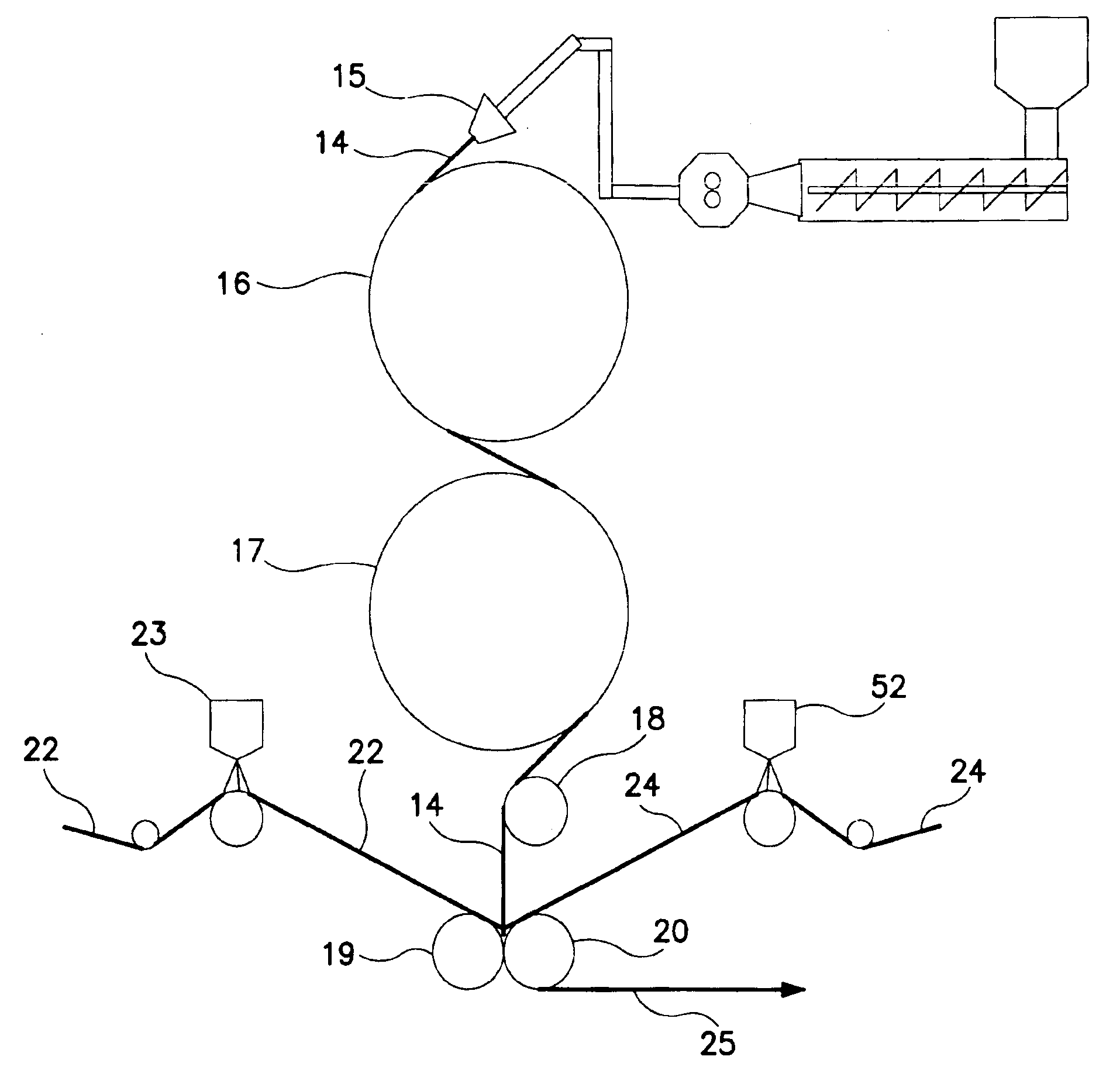
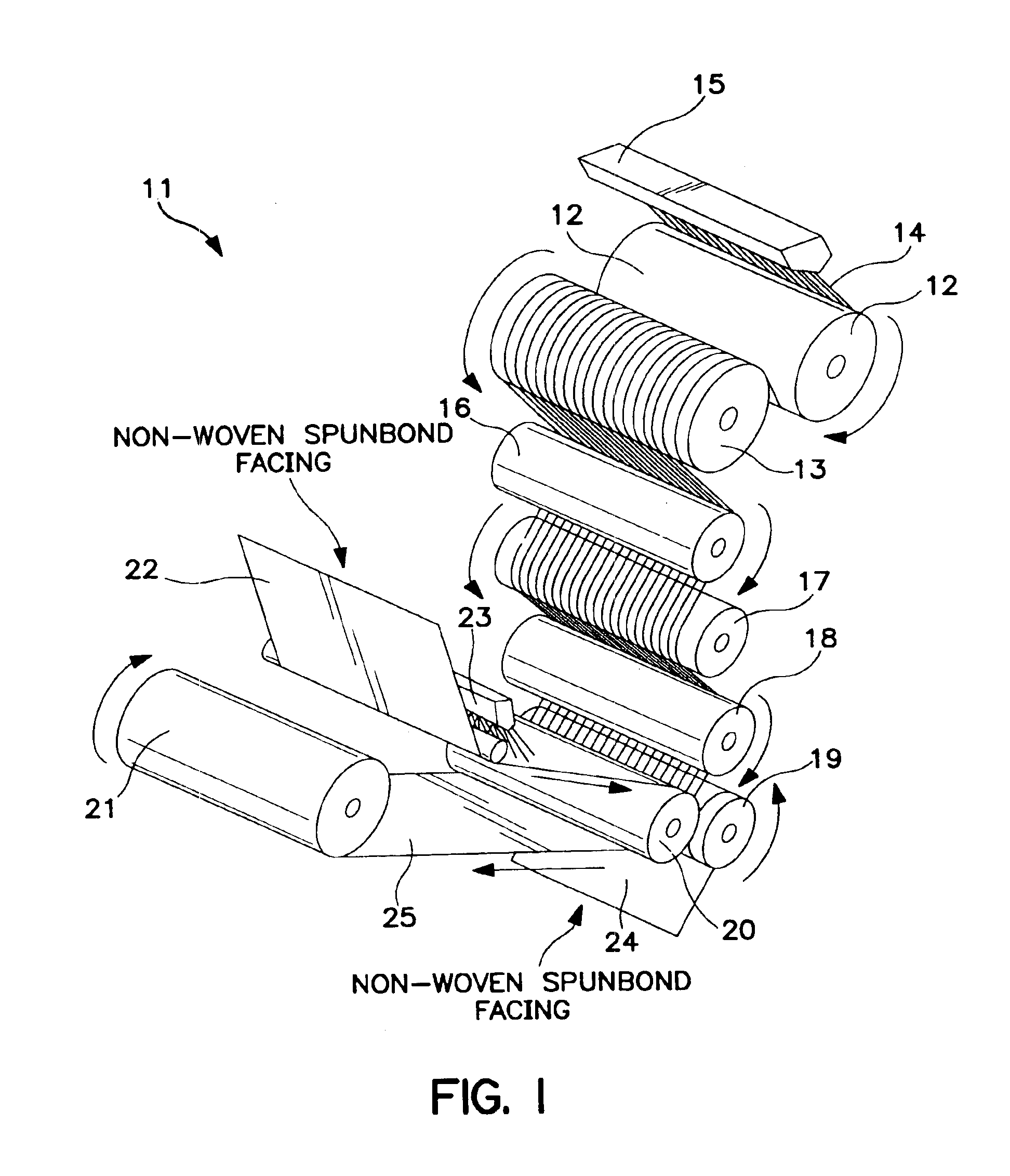
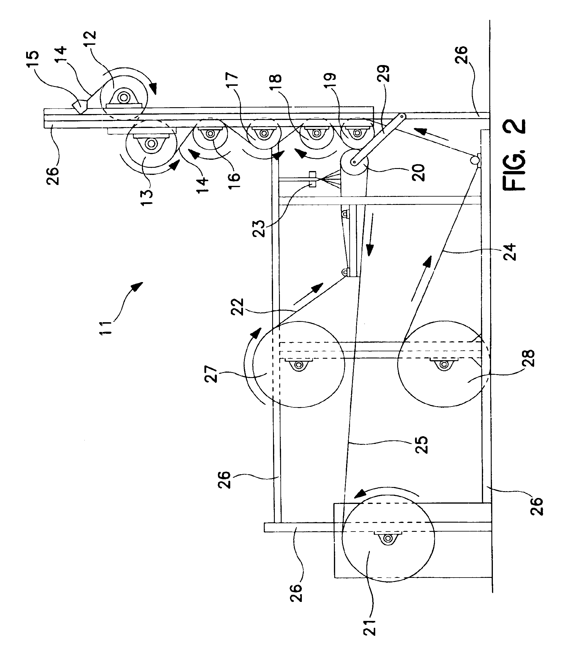
[0013]After stretching, the continuous filaments are then conveyed into position at a bonding station so that a facing of a non-elastic, less-elastic, more elastic, or identically-elastic, sheet material may be bonded to the continuous filaments. Typically, this bonding will require the application of an adhesive to the facing in order to bond the stretched continuous filaments to the facing. In certain embodiments, a second facing may be bonded to the other unattached surface of the stretched continuous filaments so as to achieve a stretchable article wherein the continuous filaments are sandwiched between at least two outer facings.
[0016]The process, which has a vertical flow, allows for several benefits over prior horizontal flow processes, as well as prior vertical processes. For example, because the continuous filaments are being extruded in a vertical direction that is approximately in line with the vertical flow of the entire lamination process, automatic re-threading of filaments when they are broken or interrupted in their travel downward may be achieved. In addition, when utilized, the series of rollers are arranged so as to provide the predetermined stretching characteristics to the continuous filaments.

Problems solved by technology

After such joining of the materials, the laminated article is then allowed to relax, which results in the inelastic component gathering in the spaces between bonding sites on the elastic sheet.
Such horizontally oriented processes may require expensive post-extrusion equipment in order to maintain the proper spacing between continuous filament strands.

Method used


Image

  • Method and apparatus for producing laminated articles
  • Method and apparatus for producing laminated articles
  • Method and apparatus for producing laminated articles

Examples


example 1

[0124]A distinction between the products produced by the present vertical laminate process and the products produced by the aforementioned horizontal laminate process (such as disclosed in Wright), is the improved uniformity of the spacing between strands and the tension variability. For example, the average filament spacing between continuous filament strands in a laminate product formed by the present process is approximately 3 mm. On the other hand, the average filament spacing between continuous filament strands in a laminate product formed by the horizontal process disclosed in U.S. Pat. No. 5,385,775 to Wright was 4 mm to 5 mm.

example 2

[0125]Another characteristic of the continuous elastic filaments formed in the present process is the denier of such filaments. For examples, at 9 grams per square meter of elastic in the laminate nip during process which corresponds to 6.4 grams per die hole per minute, running at 1100 feet per minute, with a 5.2× stretch ratio and a 50% winder ratio, the denier at the first chill roll is equal to or greater than 900; the denier at the nip is equal to or greater than 173; and the denier at the winder is equal to or greater than 347.

example 3

[0126]At 11.5 grams per square meter of elastic in the laminate nip during process which corresponds to 8.2 grams per die hole per minute, running at 1100 feet per minute, with a 5.2× stretch ratio and a 50% winder ratio, the denier at the first chill roll is equal to or greater than 1140; the denier at the nip is equal to or greater than 220; and the denier at the winder is equal to or greater than 440.


PUM

PropertyMeasurementUnit
Temperatureaaaaaaaaaa

Abstract

In the invention, a method is provided for producing a composite nonwoven fabric. A polymer is extruded into heated continuous filaments, possibly elastic, from the die head to a first chilled roller, wherein the extruder is configured to provide the continuous filaments to the chilled roller in a canted direction that is at a tangent or angle to the surface of the first chilled roller. The filaments are conveyed in a downward direction by way of chilled rollers to a nip. In a next step, the nonwoven web is sprayed with an adhesive and is laminated on the continuous filaments in the nip to form a composite nonwoven fabric. The continuous filaments move vertically downward approximately in line with the lamination process, facilitating automatic re-threading of filaments when they are broken or interrupted in their travel downward onto the chilled rolls.

Description

[0001]The present application claims the benefit of U.S. Provisional Application Ser. No. 60 / 204,307 filed on May 15, 2000.FIELD OF THE INVENTION[0002]This invention relates to a method and apparatus for producing laminated articles from elastic and / or relatively inelastic materials. Such laminated articles may be utilized in various products requiring a certain degree of elasticity, such as diapers, garments, drapes, pads, and the like.BACKGROUND OF THE INVENTION[0003]Articles requiring a degree of elasticity have been formed by combining elastic materials with inelastic, or less elastic, materials through various lamination processes. Often, such composite laminate articles will be stretchable because of the presence of the elastic material and the particular manner in which the elastic and inelastic materials have been bonded together during the laminating process.[0004]Typically, such stretchable laminates are formed by joining the inelastic material to the elastic material whil...

Claims


Application Information

Patent Timeline
IPC IPC(8): B29C48/05B29C48/345B29C70/50B32B5/26B32B37/12B32B37/14B32B37/15D01D5/16D02J1/22D04H3/16D04H13/00
CPCB29C47/30B29C47/886B29C70/504B32B5/26B32B37/144D01D5/16D02J1/22D04H3/16D04H13/006B29C47/0014B32B37/12B32B37/153B32B2305/20B29C48/05B29C48/07B29C48/345B29C48/914B29C48/9155
Inventor WELCH, HOWARD M.MORELL, CHARLES J.COOK, MICHAEL C.FITTS, JR., JAMES R.WILLITTS, DONALD V.MORRIS, MARION C.WIDEMAN, RONALD H.BREWER, JOHN A.MLEZIVA, MARK M.SALTER, KENNETH M.MAY, RAYMOND J.BOGGS, LAVADADOBBINS, LESLIE D.
Owner KIMBERLY-CLARK WORLDWIDE INC
Learn More